15
S100-F / ITB-F I&O Manual
IM101230
RD: JAN 2014
RL: 9A
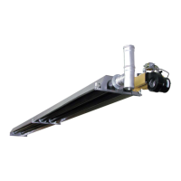
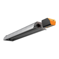
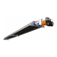
9.1 S100 / ITB STRAIGHT TUBE SYSTEM ~ BURNER AND TUBE INSTALLATION
For “U-Tube” Systems S100U / ITBU refer to section 9.2 page 17
IMPORTANT SPECIAL NOTES: READ FIRST
1. S100/ITB 100 x 20 ft: Special Tube Coupling - Refer to Section 9.3, Fig 15
2. S100/ITB 175 & 200:
Special Tube Coupling - Refer to Section 9.4, Fig 16
These input rates have an unpainted titanium alloy stainless steel first tube with a flange
(painted “white”), and an unpainted aluminized steel tube as the second tube; all subse-
quent tubes are hot rolled steel. The first tube (titanium alloy stainless steel ) will “glow
red” while heater is in operation - THIS IS A NORMAL CONDITION
3. IF a 90° elbow is to be installed in the system, refer NOW to Section 7 and the Elbow Kit
installation instructions supplied with the kit
4. TURBULATORS: Also refer to Table page 46
155 Models (150,000 Btuh): 2 ft turbulator is supplied in the Burner Kit and field installed:
155 x 40 ft heater: Insert 2 ft turbulator in end of third tube, prior to the 10 ft turbu-
lator that is factory installed in the last tube (total 12 ft turbulator)
155 x 50 ft heater: Insert in the vent end of the last tube in the system.
All other turbulators are factory installed inside tube(s) that are clearly labeled with
instruction as to where the tube(s) must be installed - Also see page 46
1) Install Hangers:
i: No closer than 3” (5 cm) and no further than 5” (10 cm) from the burner/tube flange
ii: No closer than 6” (15 cm) either side of a tube connection in the system
iii: No further than 24” (61 cm) either side of a tube connection in the system
2) With all hangers in alignment and suspended at the same height, insert first aluminized tube
section, through 4" hole into first two wire hangers.
NOTE: INSTALL THE FIRST AND SECOND TUBES (FROM BURNER END) WITH THE WELDED SEAM
ALONG THE TUBE LENGTH FACING DOWNWARD
3) Bolt burner to flange on first tube section, SEE FIGURE 8.
IMPORTANT NOTE: Models with inputs 100,000, 175,000 & 200,000 refer to section 9.3
4) Slide a Torctite tube coupler over the swaged end of the first tube, then join the second tube
over the swage in the first tube
5) Slide the Torctite coupler into position across the center of the joint - SEE FIGURE 9
6) IMPORTANT: TOURQUE THE COUPLER BOLTS TO 40 ft-lbs
7) Subsequent lengths of tube can then be installed, by joining them together swaged portion
inside the next tube and locking the joints using the Torctite coupler.
SEE FIGURE 9.
8) If there is a 90° elbow in the system refer to Section 7 and Figures 3 & 4
9 INSTALLATION OF HANGERS, TUBES AND BURNER




 To Next Page