27
S100-F / ITB-F I&O Manual
IM101230
RD: JAN 2014
RL: 9A
HORIZONTAL VENT THROUGH THE SIDEWALL:
Any horizontal portion of the flue vent system must slope downwards approximately 1/4"
per foot (63 mm/ 300 mm) toward the vent terminal - radiant tube must be level.
continued ……..
common thermostat or “ON/OFF” switch must control the two commonly vented heaters.
Install a minimum 36 inch (91 cm) length of minimum 26 gauge single walled 4” (10 cm) di-
ameter vent pipe on the system, and a minimum 12 inch (30 cm) before any Tee or Elbow.
Seal all vent connections with high temperature sealant. Vent connections must be secured
with three (3) #8 sheet metal screws uniformly spaced around the circumference of the pipe.
Any horizontal vent pipe must slope approx. 1/4” per foot away from heater
When the vent pipe passes through a cold or unheated area where the ambient temperature
is likely to produce condensation of the flue gases, the vent pipe will be insulated with a suit-
able material as approved and specified by the insulation manufacturer to withstand tem-
perature up to 460°F (238°C).
The vent system must always be adequately supported to prevent sagging.
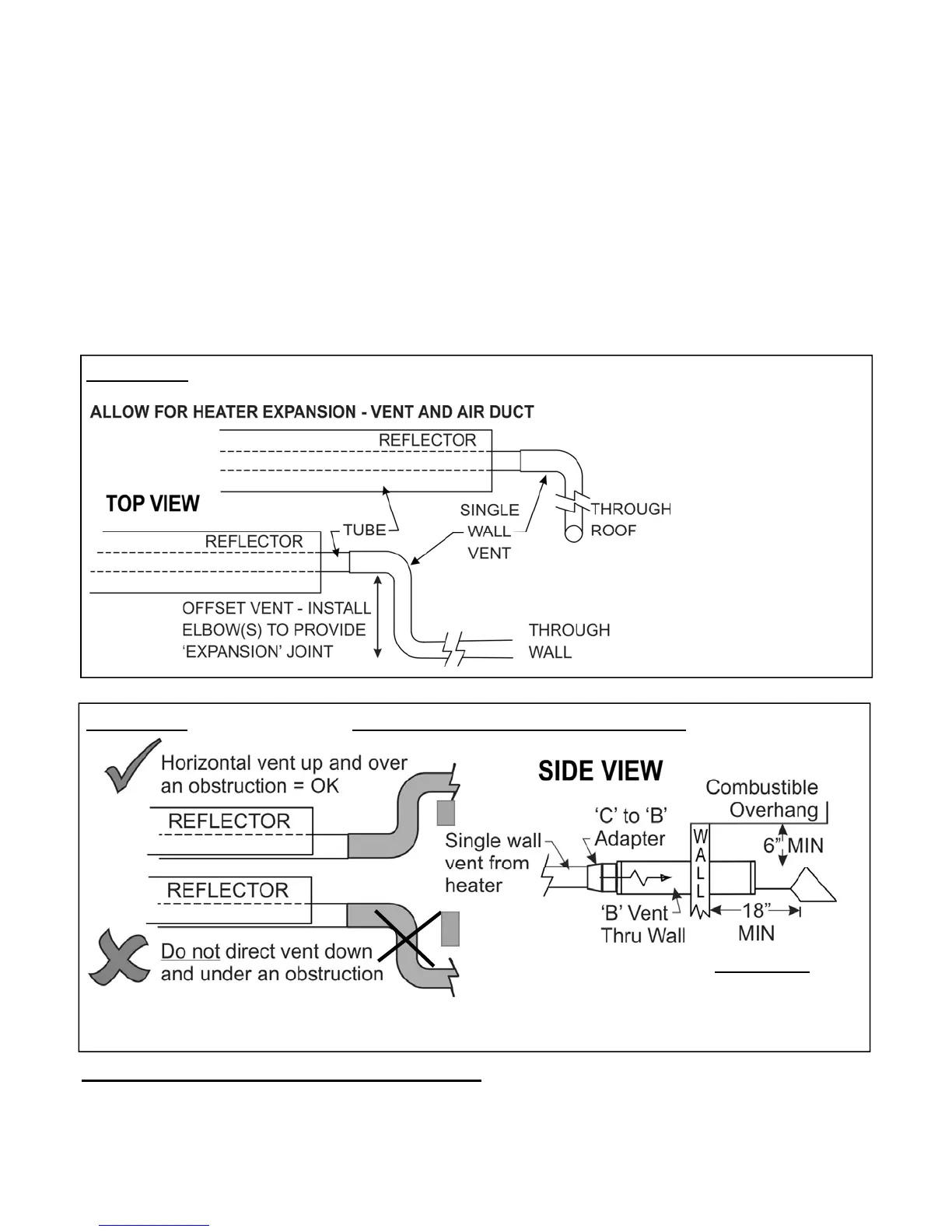
FIGURE 20 - Heater Expansion - Suggested Vent Configuration*
* Other means of slip
fit installation of the
vent and duct are ac-
ceptable providing
there is adequate al-
lowance for free ex-
pansion and contrac-
tion of the system,
and free flow of vent
gases and combus-
tion air.
FIGURE 21 - Horizontal Vent - ALL vent pipe and adapters by others
Clearances apply to JA-0528-XX 4” (10 cm) or JA-0529-XX 6” (15 cm) Vent Terminals
See notes below for use of other approved vent terminations
Clearances
 Loading...