28
2.3 PLACING THE SYSTEM
The
flexiVent
and all extensions require a dry, flat, stable workspace of 2’ x 2’ x 2’ (60 x 60 x 60
cm). Ensure that the system is stable on the workbench. If the surface is not quite level, use the
adjustable foot located under the front corner below the module to help level it and prevent
unwanted vibrations.
Once the
flexiVent
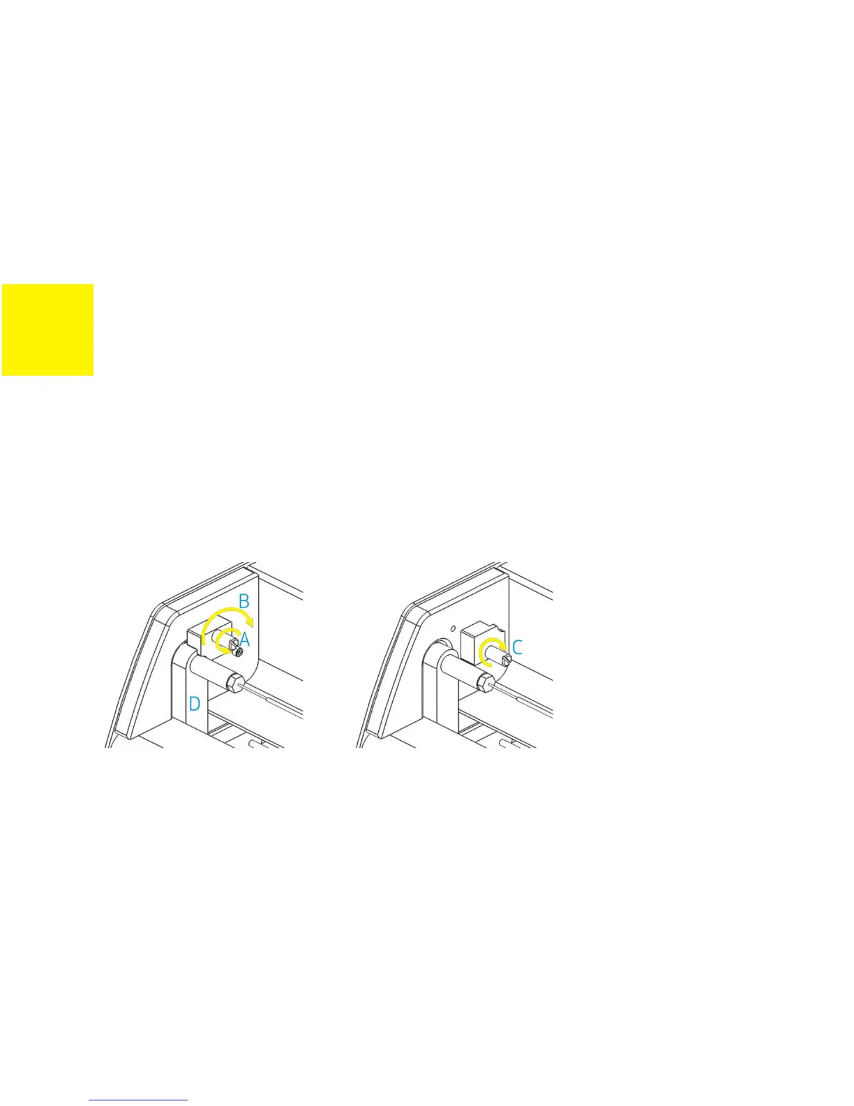
is in place, you may disengage the motor lock. To disengage the lock (refer to
Figure 2-2), remove the thumb screw (A) then rotate the motor lock to open position (B). After
disengaging the lock, reattach the thumb screw to the FX base unit (C).
FIGURE 2-2: DISENGAGING THE MOTOR LOCK
2.4 CONNECTING THE COMPONENTS
Please refer to Figure 2-1 for each of the connection locations. Plug in and unplug accessories
only when the base unit is off.