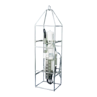
Section 2: Description of SBE 19plus V2
16
External Power
The SBE 19plus V2 can be powered from an external source (9 - 28 volts DC)
through the Y-cable connected to the Data I/O, Pump, and External Power
bulkhead connector on the sensor end cap. The internal battery pack is diode-
OR’d with the external source, so power will be drawn from whichever
voltage source is higher. The 19plus V2 can also be operated from the external
supply without having the internal battery pack installed. Electrical isolation of
conductivity is retained in units powered externally, preventing ground loop
noise contamination in the conductivity measurement.
Cable Length and External Power without Deck Unit
There are two issues to consider if powering the 19plus V2 externally:
• Limiting the communication IR loss to 1 volt if transmitting real-time
data; higher IR loss will prevent the instrument from transmitting real-
time data because of the difference in ground potential.
• Supplying enough power at the power source so that sufficient power is
available at the instrument after considering IR loss.
Each issue is discussed below.
Limiting Communication IR Loss to 1 Volt if Transmitting Real-Time Data
The limit to cable length is typically reached when the maximum current
during communication times the power common wire resistance is more than
1 volt, because the difference in ground potential of the 19plus V2 and ground
controller prevents the 19plus V2 from transmitting real-time data.
V
limit
= 1 volt = IR
limit
Maximum cable length = R
limit
/ wire resistance per foot
where I = current required by SBE 19plus V2 during communication. The
current varies, depending on operating mode:
• Profiling mode – The 19plus V2 samples and transmits data continuously.
Use the total current required for sampling (sampling, pump, auxiliary
sensor current, and communication current) in the calculation.
• Moored mode – The 19plus V2 samples, and then transmits data. Use the
communication current, 60 mA, in the calculation.
Note:
See Real-Time Setup in Section 4:
Deploying and Operating SBE
19plus V2 for baud rate limitations
on cable length if transmitting real-
time data.
Note:
Common wire resistances:
Gauge Resistance (ohms/foot)
12 0.0016
14 0.0025
16 0.0040
18 0.0064
19 0.0081
20 0.0107
22 0.0162
24 0.0257
26 0.0410
28 0.0653
Profiling Mode Examples - for 19plus V2 with standard SBE 5M pump and no auxiliary sensors
Example 1 – For 20 gauge wire, what is maximum distance to transmit power to 19plus V2 if transmitting real-time data?
Current = 65 mA (sampling) + 100 mA (pump) + 60 mA (communication) = 225 mA
R
limit
= V
limit
/ I = 1 volt / 0.225 Amps = 4.4 ohms
For 20 gauge wire, resistance is 0.0107 ohms/foot.
Maximum cable length = 4.4 ohms / 0.0107 ohms/foot = 415 feet = 126 meters
Example 2 – Same as above, but there are 4 instruments powered from the same power supply.
R
limit
= V
limit
/ I = 1 volt / (0.225 Amps * 4 instruments) = 1.1 ohms
Maximum cable length = 1.1 ohms / 0.0107 ohms/foot = 103 feet = 31 meters (to 19plus V2 furthest from power source).
Moored Mode Examples – use 60 mA communication current, regardless of 19plus V2 configuration
Example 1 – For 20 gauge wire, what is maximum distance to transmit power to 19plus V2 if transmitting real-time data?
For 60 milliamp communications current, R
limit
= V
limit
/ I = 1 volt / 0.060 Amps = 16.7 ohms
For 20 gauge wire, resistance is 0.0107 ohms/foot.
Maximum cable length = 16.7 ohms / 0.0107 ohms/foot = 1557 feet = 474 meters
Example 2 – Same as above, but there are 4 instruments powered from the same power supply.
For 60 milliamp communications current, R
limit
= V
limit
/ I = 1 volt / (0.060 Amps * 4 instruments) = 4.1 ohms
Maximum cable length = 4.1 ohms / 0.0107 ohms/foot = 389 feet = 118 meters (to 19plus V2 furthest from power source).
23