Section 2: Description of SBE 19plus V2
19
Configuration Options and Plumbing
The standard SBE 19plus V2 includes an externally mounted SBE 5M pump,
which provides a constant flow rate through the conductivity cell regardless of
descent rate. If configured with a dissolved oxygen sensor or pumped
fluorometer, the more powerful SBE 5T (titanium) or 5P (plastic) pump is used.
Any of these pumps is powered via a cable connected to the 2-pin leg of the Y-
cable (which is connected to the Data I/O, Pump, and External Power bulkhead
connector on the sensor end cap).
The 19plus V2 can be configured with a wide range of auxiliary sensors.
Three standard 6-pin bulkhead connectors on the sensor end cap serve as the
input ports for the auxiliary sensor signal voltages and provide power to the
sensors. Additionally, a standard 4-pin bulkhead connector on the sensor end cap
is provided for interfacing with an RS-232 sensor, such as an SBE 38 secondary
temperature sensor or Pro-Oceanus Gas Tension Devices (up to two GTDs can
be integrated with the 19plus V2).
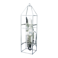
A 19plus V2 is typically deployed in a vertical position. However, when used
with an SBE 32 (full size) Carousel Water Sampler, the 19plus V2 is deployed
in a horizontal position in an extension stand below the Carousel. Pump
placement and plumbing for a horizontal mount is different than that for a
vertical mount.
Sea-Bird provides the system with pump placement and plumbing for the
desired orientation at the time of purchase. However, you may reorient the
system later as needed. Failure to place the pump and plumbing properly can
trap air, preventing the pump from working properly.
Shown below are schematics of the system configuration for vertical and
horizontal deployment. In the schematics, cables are omitted for clarity.
Secure each tubing connection with 2 cable ties.
Vertical Mount
• Place the exhaust as far from the intake as possible, so that exhaust water
is not pulled into the intake. Failure to place the exhaust away from the
intake can lead to errors in temperature data, because the pump transfers
heat to the exhaust water.
Note:
See Section 4: Deploying and
Operating SBE 19plus V2 for
pump setup and operation.
26