Section 4: Deploying and Operating SBE 19plus V2
69
Installing Anti-Foul Fittings for Moored Applications
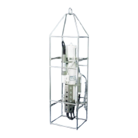
The SBE 19plus V2 is intended primarily for use as a profiling instrument, and
does not come standard with anti-foulant device cups and caps. Some
customers, finding that they use the 19plus V2 in Moored mode on occasion,
choose to install the optional moored mode conversion kit, which includes
anti-foulant device cups and caps.
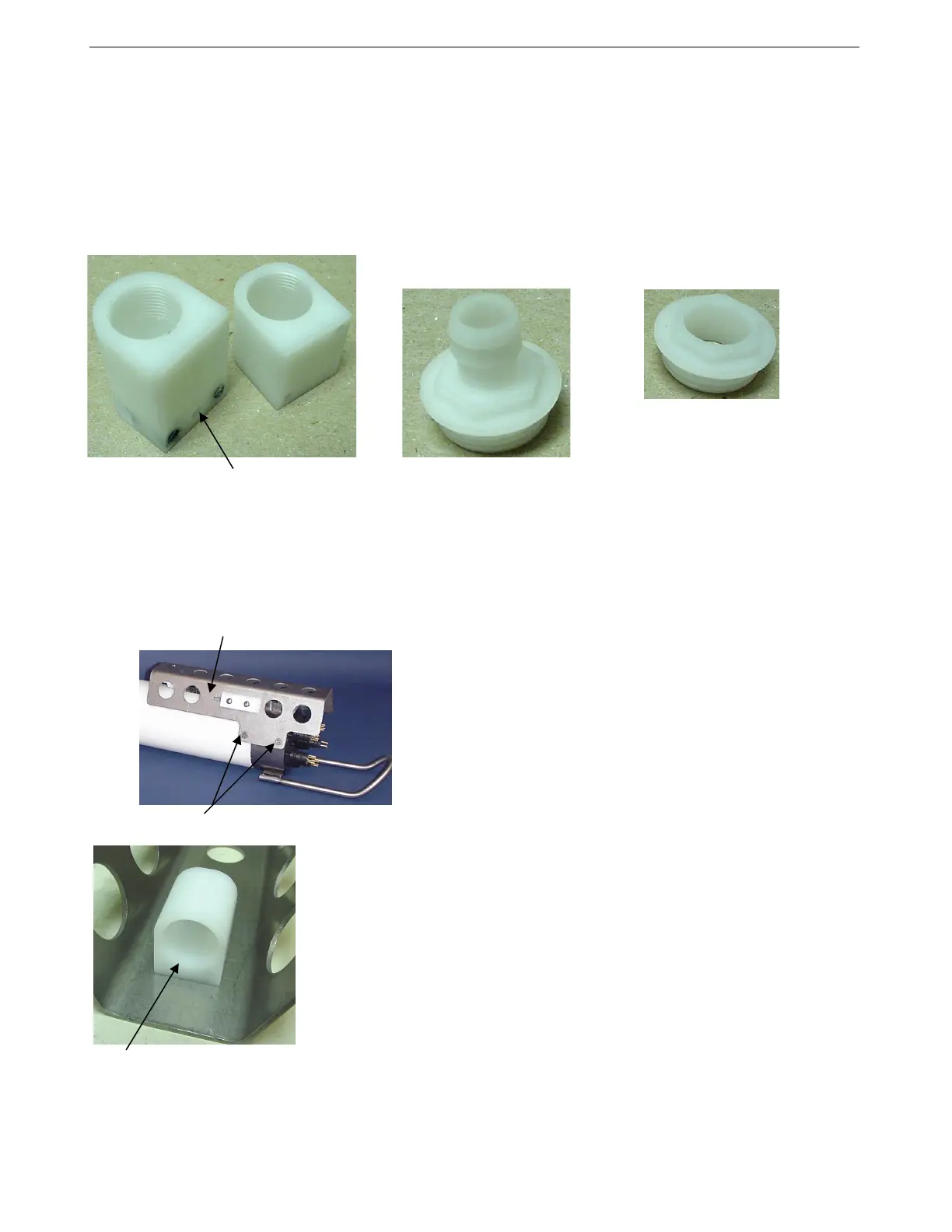
1. On pumped applications, remove the Tygon tubing from the
existing conductivity cell exhaust duct.
2. Remove the four Phillips-head screws attaching the conductivity cell
guard to the housing and end cap. Carefully remove the conductivity
cell guard.
3. Exhaust –
A. On the conductivity cell guard, remove the two small screws
attaching the exhaust duct to the guard.
B. Remove the existing exhaust duct and replace with the exhaust anti-
foulant device cup, reinstalling the two screws.
C. See Replacing Anti-Foulant Devices in Section 5: Routine
Maintenance and Calibration for details on handling and installing
the AF24173 Anti-Foulant Device.
D. Install the anti-foulant device cap to secure the Anti-Foulant Device
in the cup.
Hole for thermistor
Intake anti-foulant
device cup
Exhaust anti-foulant
device cup
Exhaust anti-foulant
device cap (barbed) for
pumped applications
Intake anti-foulant device
cap for all applications
and exhaust cap for
non-pumped applications
Note: The larger diameter of the intake cap /
non-pumped application exhaust cap helps
maintain good flow through the conductivity
cell and reduces growth of biological
material. Do not use the barbed cap in
its place.
Exhaust anti-foulant device cup
Conductivity cell guard
Exhaust
Remove screws, typical both sides
Intake
76