PV200/210 Operating Instructions
- 10 -
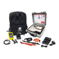
1. Hold the tips of the test probes firmly together as
shown, ensure a good electrical connection.
2. Press and hold the Rpe Null key (6).
3. The measured resistance of the test leads is shown
in the primary display until a beep is heard.
4. The Rpe display will now 0.00 and the Null icon is
illuminated on the display.
5. All subsequent measurements will take into account
the test lead resistance compensation until the
function is disabled by pressing the Rpe Null key
(6) again.
Note: A maximum test lead resistance of 10
Ω
ΩΩ
Ω
ohms can
be taken into account. If the test lead resistance is
greater than 10
Ω
ΩΩ
Ω
an error beep will indicate that
the lead Zero function has failed.
Note: For ease of use, the PV200/210 will store the lead
compensation when switched off and recall this
value when next switched on. The stored value is
only applicable to the test leads used when the
compensation measurement was made. If the test
leads are replaced the Rpe null function should be
repeated using the replacement test leads.
5.4.2
Resistance Measurement
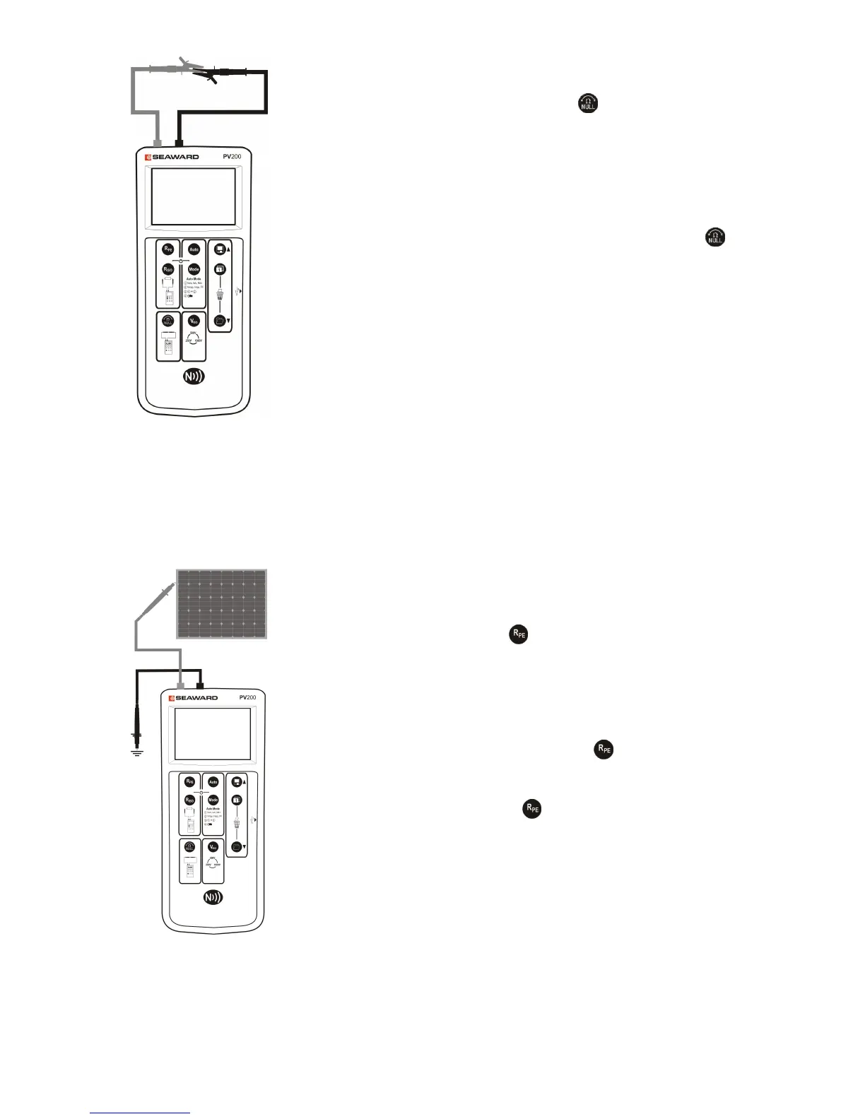
To make a single measurement:
1. Connect the red and black test leads as shown.
2. Press the Rpe key .
3. The resistance between the test probes is displayed.
To make a continuous measurement:
1. Connect the red and black test leads as shown.
2. Press and hold the Rpe key until the lock icon
appears on the display.
3. The resistance between the test probes is displayed.
4. Press the Rpe key to terminate the continuous
measurement mode.
Note: Do not connect the PV200/210 to a voltage
source while performing the resistance
measurement as this will blow the fuse located in
the battery compartment.
Note: The continuity measurement is not stored in
memory with the automatic test sequence.
Continuity measurements are stored as individual
 Loading...