IV test complete
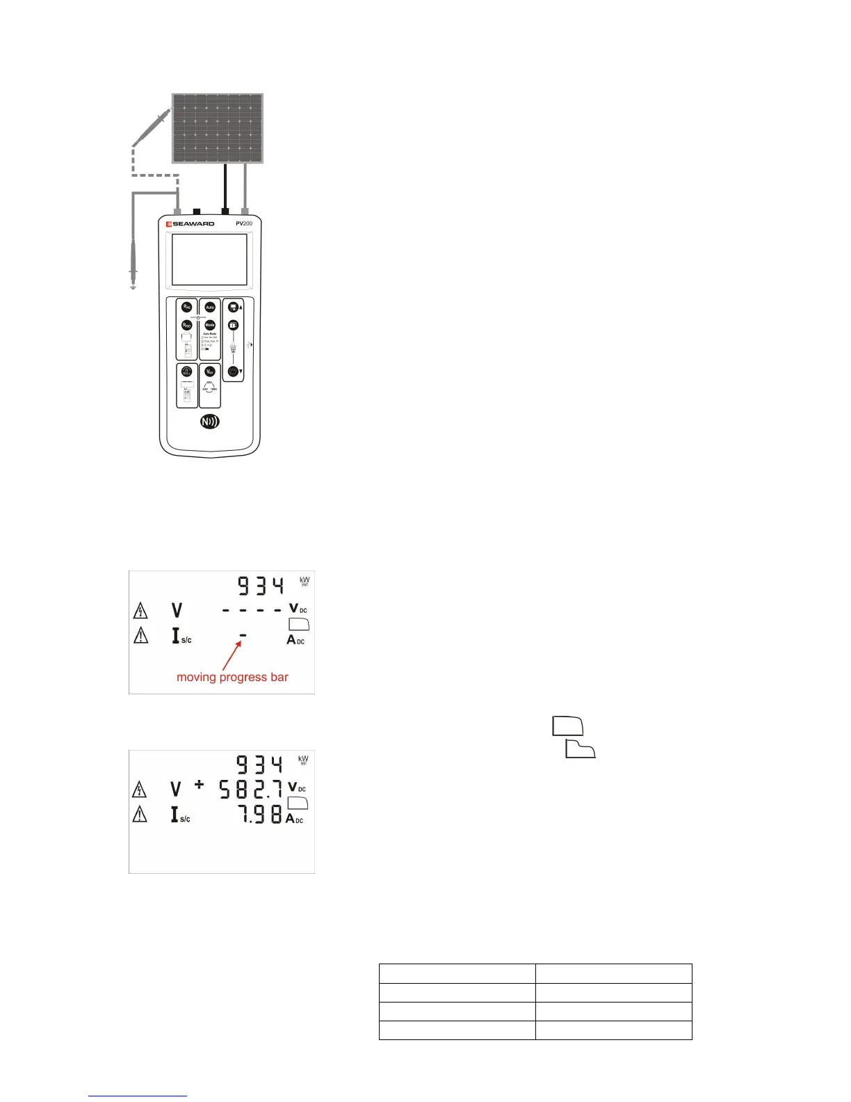
1. Connect the PV200/210 securely to the PV module
as shown using the supplied test lead adaptors or
test probes with alligator clips.
Never use test probes without alligator clips as this
may result in arcing.
Never remove any connection to the PV module
when any test is active.
2. The red test probe must be connected to earth
when measuring insulation resistance in a Mode 1
or Mode 3 sequence. Where the structure/frame is
bonded to earth, the earth connection maybe to any
suitable earth or to the array frame.
Where the array frame is not bonded to earth, a
commissioning engineer may choose to do two
tests:
a. Between array cables and earth
b. Between array cables and frame
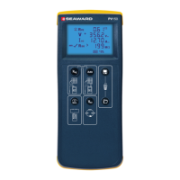
3. The PV200/210 will automatically detect any DC
voltage connected to the PV test socket inputs 8
and 9 and display the measured voltage.
4. If the PV voltage polarity is reversed, the polarity
indicator will flash a cross icon next to the voltage
icon.
5. If the incoming voltage is >30v then the shock
hazard icon will flash.
6. Press the Auto key and the Solar PV200/210 will
automatically perform the following the selected test
sequence.
7. If an I-V curve measurement has been selected,
progress is shown by moving dashes in the Is/c
display field.
8. When an I-V curve measurement is complete, the
measured values for Vo/c and Is/c will appear on
the display.
9. If the fill factor is ≥60 the icon is displayed
10. If the fill factor is <60 the icon is displayed to
indicate that a problem may exist with the PV
module or system under test. The measured I-V
curve can be examined in detail on-site using the
PVMobile App.
11. The measurement results will remain on the LCD for
20 seconds or until a key is pressed.
12. If the insulation test has been performed then a tick
or cross will be displayed next to the measurement
indicating whether the result is above or below the
threshold values shown in the table below.
 Loading...