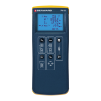
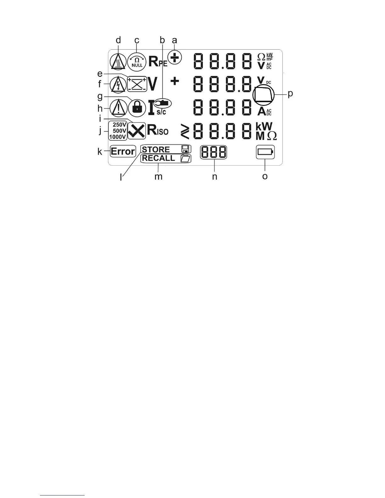
Figure 3 LCD display icons
a. Rpe voltage polarity. For AC voltages alternating + and – is shown.
b. Current clamp measurement active.
c. Rpe Null offset - indicates that test lead resistance offset is active.
d. Caution – hot surface. If this icon appears, the PV200/210 must be disconnected
immediately from the PV system until the icon is no longer shown on the LCD.
e. Solar module polarity indicator – indicates the polarity of the DC voltage applied
to the PV test terminals e.g. correct or reversed
f. Caution – hazardous voltage detected.
g. Rpe test lock – active when continuous Rpe measurement has been enabled.
h. Caution – refer to operating instruction. When this icon is active, the operating
instructions must be followed to avoid risk of danger.
i. Riso PASS/FAIL – indicates whether the measured insulation resistance is above
or below the factory set acceptable value.
j. Insulation Test Voltage selection – indicates the test voltage selected for
insulation resistance measurements.
k. Error – Refer to the specific error codes for further details.
l. STORE - indicates that you can now store the test result shown on the display or
that the test result is being stored.
m. RECALL – the data shown on the LCD has been recalled from the onboard
memory.
n. User Memory display – indicates the memory location of the results stored or
recalled on the LCD.
o.
Battery status icon.
p. I-V status icon / low fill factor indicator
 Loading...