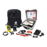
voltage source
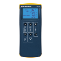
2. The PV200/210 will automatically measure the
voltage between the probes.
3. The polarity of the voltage is shown using the
icon to the left of the displayed voltage.
4. AC voltages are indicated by alternating + and –
symbols.
5.6
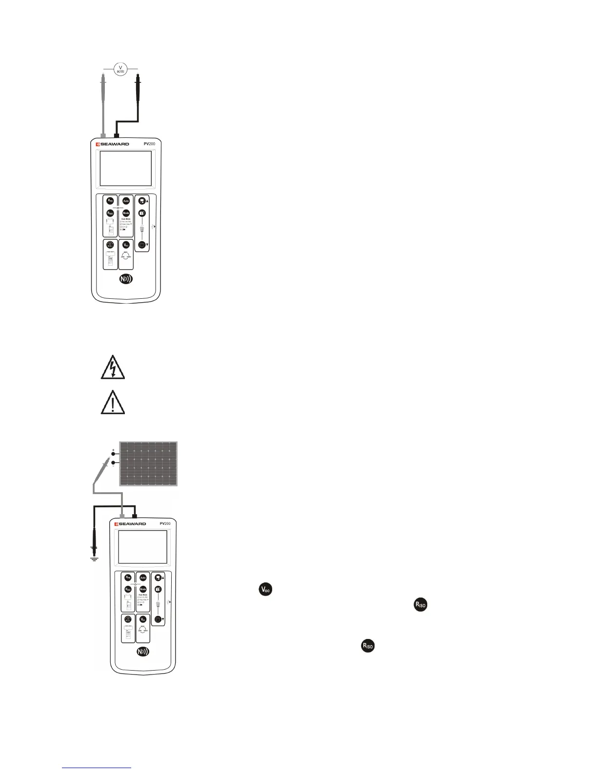
Point to Point Insulation Resistance (Riso) Function
Always ensure that the circuit under test is electrically isolated.
If the test probes are connected to a voltage >30V, the measured voltage
will be displayed on the LCD and the Riso measurement function is
inhibited.
To make a single measurement:
1. Connect the red and black test leads as shown.
2. Select the required test voltage using the Viso key.
3. Press the Riso key.
4. The resistance between the test probes is displayed.
To make a continuous measurement:
1. Connect the red and black test leads as shown.
2. Select the required test voltage using the Viso key
.
3. Press and hold the Riso key until the lock icon
appears on the LCD.
4. The resistance between the test probes is displayed.
5. Press the Riso key to terminate the continuous
measurement mode.
Note: Do not connect the PV200/210 to a voltage
source while performing the resistance
measurement as this will blow the fuse located in
 Loading...