XT Controllers for NLV-CN Compressors
Page 26 / 27
Read out on the display:
It’s possible to select between a variety of different parameters to be shown on the display, “Display
temperature” (099). With “Display minimum limit temperature” (r06) the minimum read out can be limited
downwards. Furthermore, it’s possible to select, whether the temperature read out on the display must be
in °C or °F. The parameter “Temperature unit” (r05) is set to °C as default.
Restrictions:
All sensor inputs include a detection of open or shorted sensors. A sensor alarm will only be reported
and sent out if the sensor is being used by a function. If a sensor fails the sensor readout will be set to
-300 °C for an open circuit and +300 °C for a shorted sensor. If the sensors S1/S2 are used in a weighted
combination and one of the sensors fails, the sensor with no failure will be used and weighting is disabled.
An alarm will be sent out for the defective sensor.
Dependencies:
The step resolution for the display will be defined by the parameter “Display temperature step resolution”
(o15). Please refer to chapter Display.
Parameter Function Code
Multiple
Apps
Min. Max.
Default
Setting
Unit
S1 temperature U12 -300 +300 RO °C
S2 temperature U16 -300 +300 RO °C
S3 temperature U76 -300 +300 RO °C
S4 temperature U09 -300 +300 RO °C
S1/S2 temperature U98 -300 +300 RO °C
T
act
temperature U17 -300 +300 RO °C
T
haccp
temperature U99 -300 +300 RO °C
T
disp
temperature (displayed on MMI) U56
-50.0
(see r06)
+300 RO °C/°F
T
alarm
temperature U57 -300 +300 RO °C
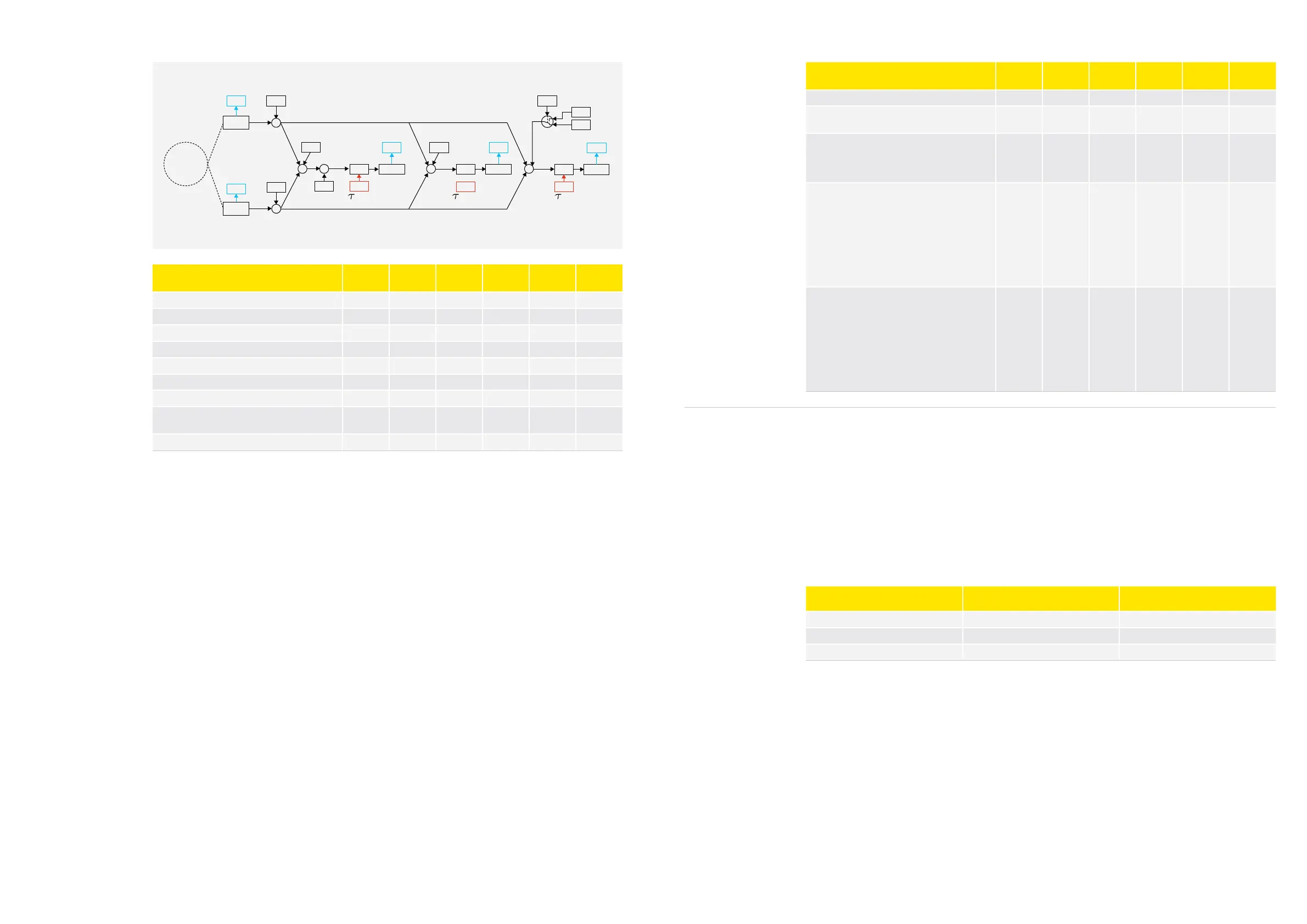
Actual
Cabine
temperature
r09
r04
F
o91 o90
F
F
o92
TS3/S4
o17
S4 weight TS3/S4
S4 weight Talarm
S4 weight Tact
Tact
act
Night
Talarm
alarm
S3/S4 offset S3/S4
S4 offset
+
+
+
S3
U16
U98 A36 U57 U17
r61
r15
S4
Parameter Function Code
Multiple
Apps
Min. Max.
Default
Setting
Unit
Temperature unit (°C = 0/°F = 1) r05 0 1 0 °C/°F
Display minimum limit temperature
(-300 if used sensor value is faulty)
r06
-50
(-300)
20 -50 °C
Display temperature step resolution
1 = 0.1°K
2 = 0.5°K
3 = 1.0°K
o15 x
1
(0.1)
3
(1.0)
2
(0.5)
-
(°K)
Display temperature
0 = S1/S2 (U98)
1 = T
alarm
(U57)
2 = T
act
(U17, default)
3 = T
haccp
(U99)
4 = S1 (U12)
5 = S3 (U76)
6 = S2 (U16)
7 = S4 (U09)
o99 x 0 7 2 -
Selection of sensor for the HACCP function.
0 = None
1 = None
2 = S2/S1
3 = T
alarm
4 = T
act
5 = S4
6 = S3
Note: If “h11 = 0”: T
haccp
(U99) = 300.00°C
h11 x 0 6 0
4.4.
Temperature
Logger
The NLV controller has an internal temperature logger that can log a predefined temperature directly
into the memory of the NLV controller. It is possible to attach an alarm to the logger, which will indicate a
warning when the upper or lower alarm limits are exceeded, and when the alarm delay timer has elapsed.
Functional description:
Using the parameter “Selection of sensor for the logger function” (h11), it is possible to select a
temperature sensor or an internal temperature calculation for the temperature logger. If no sensor is
selected, the logger will not begin. Logging speed is determined by ”Log interval” (h01). The number of
logs is limited to 1,000. This means that the duration of the logging period depends on the number of logs.
For logging duration, please see the following table.
Logging Interval Maximum log duration in hours Maximum log duration in days
15 minutes 250 10 days
30 minutes 500 20 days
60 minutes 1000 40 days
 Loading...