XT Controllers for NLV-CN Compressors
Page 10 / 11
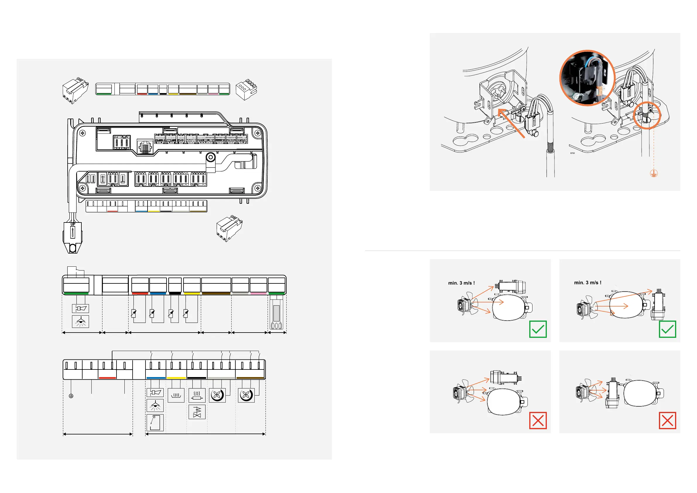
2.2.
Controller
Connections
8936-5
Spade connectors 6.3 x 0.8
RAST 2.5
RAST 5
RJ45 connector
L
L
N
PE
PE
N
RL2
N
RL1
N
RL3
N
N
RL5
RL6
RL7
RL4
N
S
NO
NC
RL8
Modbus
DIO1
DIO2
Displa y
AIO
S4
S3
S1
S2
GND
GND
GND
GND
GND
GND
GND
12V
I/O
12V
I/O
12V
open
open
open
Aout 1
Aout 2
Ain2
Ain1
Inp.
Inp.
Inp.
Inp.
GND
12V
I/O
RAST 5
Sensors
Relays
Display
DIO1/2
AIO
Modbus
Mains
100-240 V
50/60 Hz
N
L
L
L
N
PE
PE
N
RL2
N
RL1
N
RL3
N
N
RL5
RL6
RL7
RL4
N
S
NO
NC
RL8
Modbus
DIO1 DIO2
Displa y
AIO
S4
S3
S1
S2
GND
GND
GND
GND
GND
GND
GND
12V
I/O
12V
I/O
12V
open
open
open
Aout 1
Aout 2
Ain2
Ain1
Inp.
Inp.
Inp.
Inp.
GND
12V
I/O
>
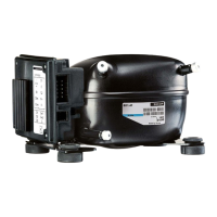
Ensure proper airflow of 3 m/sec. at both compressor and heat sink of electronic unit.
.
>
Ensure that the controller doesn’t block for the airflow to the compressor.
.
2.4
Mounting:
Airflow
2.3.
Earthing the
Compressor and
Controller
>
For optimum EMC performance, the copper shield on the controller cable must be fastened properly in
the clip at the compressor.
>
Compressor and controller must be connected to PE (Protective Earth) to avoid risk of electrical
hazard.
>
All protective earth lines, PE, in the application must be collected to one star point. This prevents loop
currents which could cause problems concerning the electronic components, communication lines,
and sensors. The star point is normally a screwed terminal on the chassis.