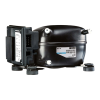
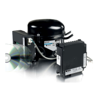
XT Controllers for NLV-CN Compressors
Page 50 / 51
Furthermore, all temperature measurements can be read out. To check the correct reading, compared to
the actual sensor temperature the below table can be used.
NTC temperature table for S1, S2, S3, and S4
Access levels:
Once the service level code has been entered, the access codes for the different access levels can be
modified:
T (°C)
B25/100 = 3980 K, R25 = 5000 Ω, TR = 0°C
Rnom( Ω)
Rnom( Ω) Rnom( Ω)
-40 169160 159350 178970
-35 121800 115390 128200
-30 88766 84552 92979
-25 65333 62555 68111
-20 48614 46778 50450
-15 36503 35291 37715
-10 27680 26883 28478
-5 21166 20646 21686
0 16330 16003 16657
5 12696 12386 13006
10 9951 9670 10232
15 7855 7604 8105
20 6246 6025 6467
25 5000 4806 5194
30 4029 3859 4198
35 3266 3118 3414
40 2665 2535 2794
45 2186 2073 2298
50 1803 1705 1901
55 1495 1419 1581
60 1247 1172 1321
65 1044 979 1110
70 878.9 821.7 936.1
Code Function Description
o05 Access code end user Access code for the end user level on the display
o06 Access code installer Access code for the installer level on the display
o07 Access code service Access code for the service level on the display
o08 Access code OEM lab Access code for the OEM level on the display
Activation of outputs:
Before it is possible to activate the relays ON/OFF, the service mode must be activated via the parameter
“Service mode” (p83). There are 5 different service modes available:
1. Normal, control mode
2. Service mode
3. Customer lab mode, only to be used in the OEM lab for running special approval test, only accessible
with OEM key
4. Secop test mode
5. Supply chain test mode
When the NLV controller is set in service mode, all relays are switched off, and the compressor speed is
set to zero. When the controller is set back into normal control all relays are set back into same state as
before entering the service mode, and the compressor resumes with the same capacity.
The 8 relays R1 to R8 can be set to ON and OFF with the parameters “Relay X Manual control” (P84 to
P91). When the controller is taken out of the service mode and put into the normal control mode, the
normal cabinet control will be resumed regardless of the actual states of the relay in the service mode.
4.21.
Rail Heater Control
The rail heater function is intended for glass heating, rail heating, or frame heating.
The rail heater is controlled by on and off pulsing of the rail heater relay.
There are two ways to control energy consumption:
>
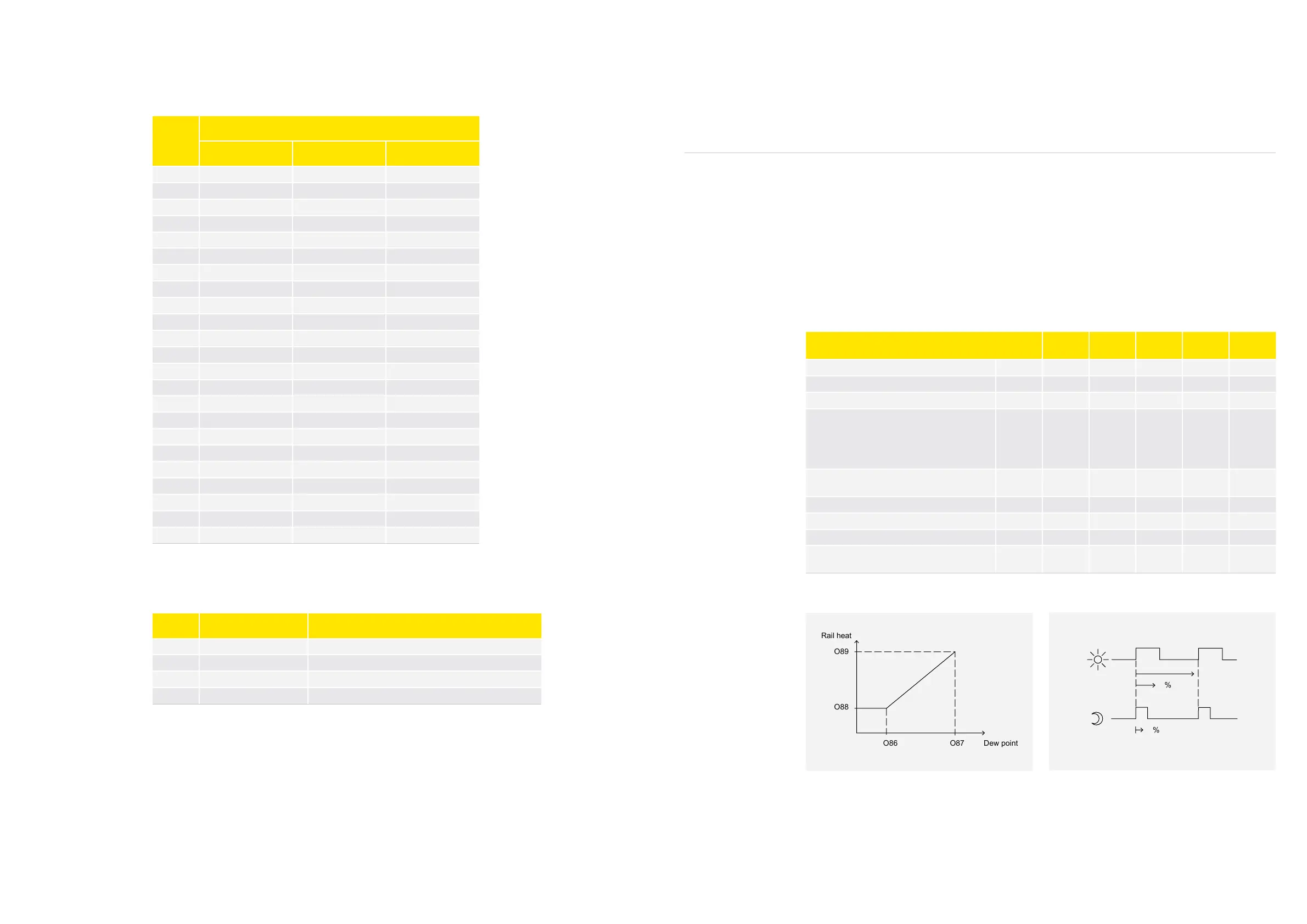
With different duty cycle rates during night and day condition
>
With different duty cycle rates based on a %RH signal received from the front-end system
The rail heat is off when the controller is in stop mode. During the defrost, melt, and case-cleaning
modes, the heater is on 100%. During normal operation, the function is determined by parameter O85.
The following graphics illustrates the function of the rail heater control
Parameter Function Code
Multiple
Apps
Min. Max.
Default
Setting
Unit
Rail heat on-time during daytime operation o41 x 0 100 100 %
Rail heat on-time during nighttime operation o42 x 0 100 100 %
Rail heat period time (on-time + off-time) o43 x 10 60 10 min.
Rail heat control
0=not used
1 = pulse width control with timer function
(o41, o42, and o43)
2 = pulse control with dew point function
o85 0 2 0
Dew point value where the rail heat is mini-
mum
o86 -10 50 8 °C
Dew point value where the rail heat is 100% on o87 -9 50 17 °C
Lowest permitted rail heat effect in % o88 0 100 30 %
Highest permitted rail heat effect in % o89 0 100 100 %
Dew point value received from master control-
ler
o83 -10 50 - °C