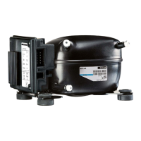
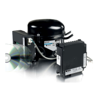
XT Controllers for NLV-CN Compressors
Page 16 / 17
2.7.5.
Connection of
Power Outputs
>
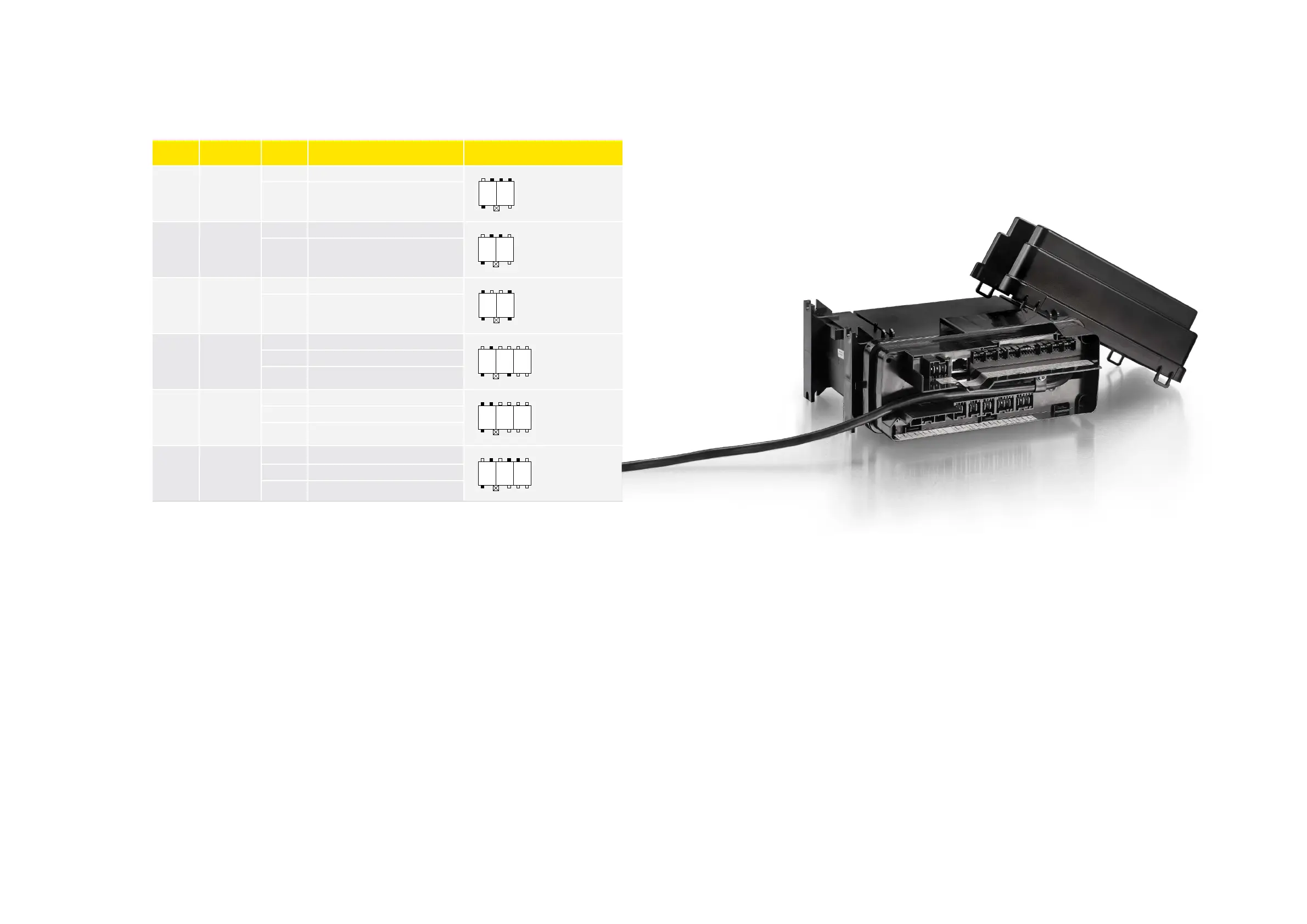
All connector outputs on the power board are pre-wired with neutral and live switched over the relay.
>
The connector outputs are mechanically coded to prevent wiring errors in production and service.
>
Connectors 1 to 4 are compatible with 105N46xx series controllers.
>
The coding scheme shows the position of keying and locking latches. Black means the key is present.
>
Max. load for individual relays: RL1–RL7:
• 8 A res., 30,000 cycles
• 2(2)A, 100,000 cycles
• 12 RLA, 2 FLA, 100,000 cycles
>
Max. total load for RL1–RL7 depends on compressor status:
• max when compressor is stopped: 16A (electrical defrost)
• Max when compressor is running: 6A
>
Max load: RL8: 2A res, 100.000 cycles
Name Connector Pin Type Connector
RL 1 1
1 Live switched, N.O.
P
1
K
2
1a 1b 2a 2b
1c 2d
2 Neutral
RL 2 2
1 Live switched, N.O.
P
1
K
2
1a 1b 2a 2b
1c 2d
2 Neutral
RL 3 3
1 Live switched, N.O.
P
1
K
2
1a 1b 2a 2b
1c 2d
2 Neutral
RL 4
RL 5
4
1 RL4 output, live switched, N.O.
P
1
K
2 3
1a 1b 2a 2b 3a 3b
1c 2d 3a 3b
2 RL5 output, live switched, N.O.
3 Neutral
RL 6
RL 7
5
1 RL6 output, live switched, N.O.
P
1
K
2 3
1a 1b 2a 2b 3a 3b
1c 2d 3a 3b
2 RL7 output, live switched, N.O.
3 Neutral
RL 8 6
1 N.C.
1
K
P
2 3
1a 1b 2a 2b 3a 3b
1c 2d 3a 3b
2 N.O.
3 Base pin