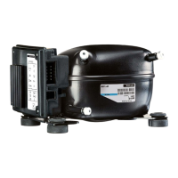
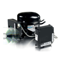
XT Controllers for NLV-CN Compressors
Page 36 / 37
Parameter Function Code
Multiple
Apps
Min. Max.
Default
Setting
Unit
Condenser fan mode:
0 = Off
1 = Run with compressor
2 = Speed controlled by sensor S3
3 = Always run unless stopped
4 = Run at low speed when compressor stopped
F11 x 0 4 1 -
Condenser fan high speed temperature (S3) F12 x -50 85 35 °C
Condenser fan low speed temperature (S3) F13 x -50 85 30 °C
Condenser fan alarm temperature (S3)
Set to zero the function is disabled
F14 x 0 85 0 °C
Condenser fan low speed as function
of compressor speed
0 = constant high speed
4500 = constant low speed
F15 x 0 4500 2500 rpm
Condenser fan speed during defrost
0= Off
1= Low speed
2= High speed
F16 x 0 2 0 -
4.9.
Condenser
Fan Control
The condenser fan can be controlled separately during normal operation and defrosting. To reduce noise
and power consumption, the controller supports AC fans with 2-wire speed control.
Speed control can be done either by compressor speed or by a temperature sensor (S3) placed at the
condenser. The sensor can also be used for issuing a warning or alarm in case of blocked condenser or
defect condenser fan.
To configure the speed control, both parameters for fan control and relays must be set.
1. If F11 is set to 1, the fan speed is determined by the speed of the compressor.
a. If the compressor speed is below F15, the fan will run at low speed.
b. When the speed of the compressor has increased by 200 rpm over F15, the fan returns to high speed.
2. If F11 is set to 2, the fan follows the compressor, but the speed of the fan depends on the S3
temperature. When S3 is above or equal to F12 it runs at high speed. When below F13, it will run at low
speed. If sensor S3 has a failure the fan will run at full speed.
3. Defrost control:
The condenser fan can be stopped during hot gas defrost to optimize the power for defrosting. If the
controller becomes too hot, the condenser fan will be started and run until defrosting has finished.
4.10.
Defrost Control
The defrost control can handle systems with hot gas, natural, and electric defrosting
Scheduling of defrost can be based on a timer counting of the elapsed time to next defrost or real time
clock controlled hours.
The defrost execution contains algorithms to minimize risk of liquid return to the compressor.
1. After defrost has started, the hot gas valve is activated.
2. The compressor is kept stopped for the time defined by parameter d43
3. The compressor runs at low speed for the time defined by parameter d44.
4. After d44, the compressor continues at high speed until end of defrost.
During the defrost, the condenser fan can be stopped to improve the defrosting. The fan will turn on in
case the electronic unit needs cooling.
Parameter Function Code Min. Max.
Default
Setting
Unit
Defrost temperature U37 -300.00 +300.00 RO °C
Defrost stop temperature d02 0 25 6 °C
Max. defrost duration d04 o/skip 240 45 min.
Drip off time d06 0/skip 60 0 min.
Delay for evap. fan start after defrost d07 0 60 0 min.
Evap. fan start temperature d08 -50 0 -5 °C
Evap. fan cut-in during defrosting d09 0/no 1/yes 1/yes -
Defrost sensor:
0 = Stop on time
1 = S4
2 = S2
3 = S1
d10 0 3 0 -
Heat in drip tray. Time from defrosting stops to
heating in the drip tray is switched off.
d20 0 240 30 min.
Drain preheat. Time to heat up the drain be-
fore starting defrosting.
d40 0/skip 240 0 min.
Pull-down time. The maximum time that the
system is doing pull-down after defrosting.
d41 0 240 0 min.
Hot-gas capacity. The capacity that is used for
hot gas defrosting. Capacity after d44.
d42 0 100 0 %
Compressor time at 0 speed after hot gas start d43 0 60 0 min.
Compressor time at low speed after d43 d44 0 60 0 min.
Max hold time after coordinated defrost o16 0/skip 240 20 min.
Capacity during drip off time L95 0 100 0 %
Capacity during drain preheat L96 0 100 0 %
 Loading...