Page 64 / 65
7
MODBUS
The Modbus used in the controller is based on a RS-485
physical layer. Timing is controlled by an UART. Data is
transmitted over a differential pair of wires. D1 is the
non-inverted representative of the UART signal; D0 is the
inverted signal of the UART.
Please note: the RS-485 is not comparable with a RS-
232. Both lines on a RS-485 carry the same data, however
on a RS-232, one line is for transmission and one is for
receiving. The logic is based on the voltage level, D0 > D1
= 1 and D0 < D1 = 0. Both lines refer against each other,
whereas RS-232 signals always refer to GND.
Communication is controlled by a bus master. The required
supported bus speeds are 9.6 kbit and the standard bit rate
19.2 kbit; other standard bit rates are not supported.
7.1.
Short Description
of all Bus Parts
Knots
Knots are all devices on a bus which can receive and/or transmit data.
Bus master (head unit, gateway)
The bus master is an active knot which starts the communication process requesting data from other
passive knots. There is always only one bus master allowed.
Secondaries
Secondaries such as the controllers are passive knots which should only transmit data when a master
requests them. A PNU list containing the data addresses is necessary to setup the bus master.
Data line
The data line in a RS-485 based Modbus is a differential pair. A differential pair is built by 2 wires: D1
and D0. The logic is based on the voltage level, D0 > D1 = 1 and D0 < D1 = 0. The differential pair should
always be together in a twisted pair.
For a minimum setup a bus master, a secondary, and the data line between them is necessary. All the
following items are recommended; they will increase the performance and reliability significantly.
Common line
The common line is required to bring all transceivers to one potential level.
BIAS resistor (RBIAS) (also called balancing or polarization)
The voltage level on the bus line is not defined when no transceiver is active, so it is necessary to pull D1
and D0 to the bus-idle-state (D1 = 1, D0 = 0).
Termination resistor (RT)
Must be installed at each end of the bus. They must suppress reflections of the data signal at the end of
the data line.
Shield
The cable which is used should be shielded to protect the data line against outside disturbances.
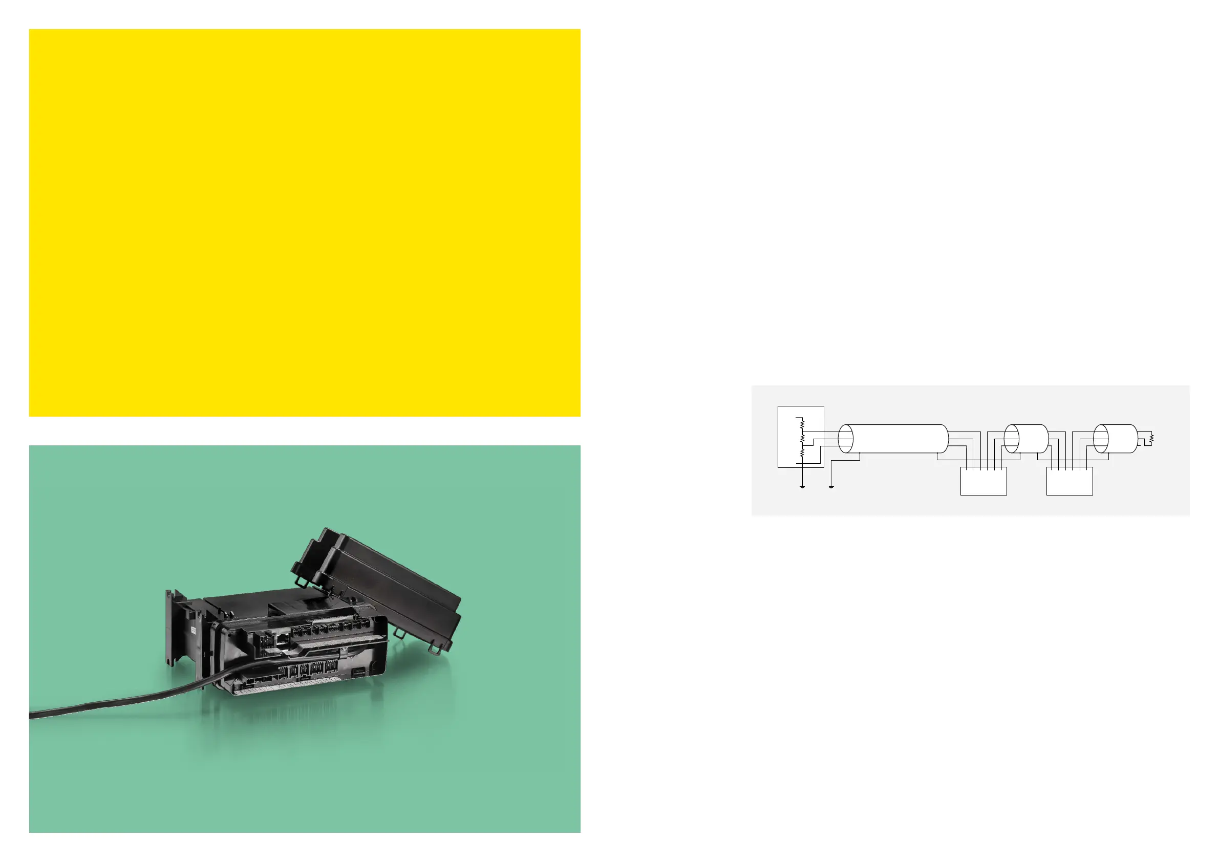
Equivalent circuit diagram of the Modbus
Central unit
SLV
COM
A
B
B
A
COM
SLV
COM
A
B
B
A
COM
Secop
17.10
R
R
R
BIAS
BIAS
T
R
Recommended electrical equipment:
The controller is designed to use standard network equipment with RJ-45 CAT5 cables and RJ-45
Y-distributors with a 1:1 pin connection. Make sure that the adapter is a shielded type, otherwise the
shield will end behind the first Y-connector. With these parts it is very easy to build up the connections
between the controller and bus master. Screw terminals and D-shell 9 are also accepted by the standard
and could be used, while the controller is designed to support RJ-45.
Please note: Connection of a crossed cable in a 2-wire Modbus system can cause damage.