Page 58 / 59
5
ANALOG AND
DIGITAL INPUTS
AND OUTPUTS
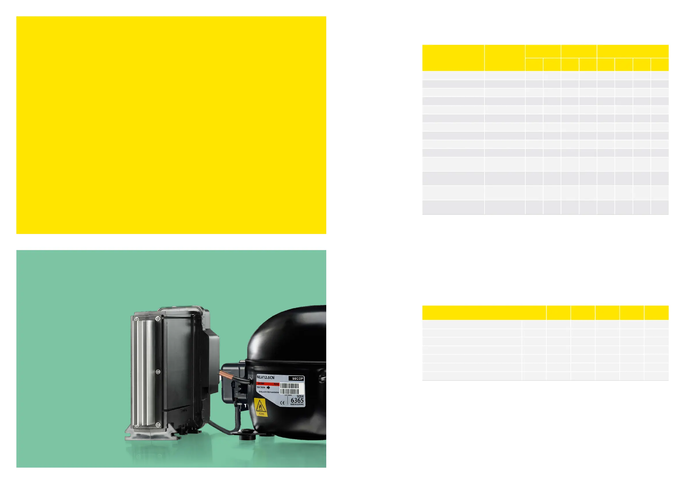
The following table shows the different options for the analog and digital IOs
.
>
Analog functions for AIO1 not yet implemented, but the inputs can be used for digital signals
.
>
Only one IO can be configured for same function, except for door switch. In case of double configuration
an alarm will be activated
.
>
If a short-circuit is made of the 12V supply, the controller will disable the 12V supply, all digital and
analog ports, including display. The controller, temperature sensors, relays and the Modbus connection
will still be active
.
>
If the 12V supply is overloaded, the controller will disable the 12V for 10 seconds, then enable it for 1
seconds. This will continue until the overload disappears
.
*Switch: Contact with 2 stable positions (open/closed).
**Push-button: Contact with 1 stable position (open) and only closed when pushed.
Parameter Function Code
Multiple
Apps
Min. Max.
Default
Setting
Unit
DIO1 function o02 Yes 0 9 0 -
DIO2 function o20 Yes 0 10 6 -
Analog input 1 function o22 Yes 0 10 0 -
Analog input 2 function o23 Yes 0 10 0 -
Analog output 1 function o24 Yes 0 2 0 -
Analog output 2 function o25 Yes 0 2 0 -
Alarm time delay on the GIO input A27 x 0 240 0
min.
Signal Type
DIO1 DIO2 AIO
In Out In Out In-1 In-2 Out-1 Out2
Door Switch* x x x x
Blind cover Switch x x x x
Main switch on/off Switch x x x x
Defrost Push-button** x x x x
Case clean Push-button x x x x
Alarm Open drain x x
Application change over Push-button x x x x
Night Push-button x x x x
Light Push-button x x x x
SWI Communication x x
Evap. Pressure
(Not implemented yet)
Analog signal x x
Cond. Pressure
(Not implemented yet)
Analog signal x x
Cond. Fan Speed
(Not implemented yet)
Analog signal x x
Expansion Valve
(Not implemented yet)
Analog signal x x