XT Controllers for NLV-CN Compressors
Page 46 / 47
4.17.1.
Application-
Related Alarms
4.17.2.
Alarm
Acknowledgement
There are 3 different ways to acknowledge alarms:
>
By pushing the reset button on the local display, remotely from a front-end system or auto
acknowledge by the controller.
>
In the factory setting, the controller is not set to auto acknowledge.
>
The function is enabled by setting the parameter “Auto acknowledge” (o84) different to zero.
4.18.
Safety Function
4.19.
Event Logging
The safety stop will disable all peripheral components, such as fans, light, and compressors in case of a
fatal failure in the refrigeration system, typically caused by a defective hot-gas valve.
>
When the compressor runs and the temperature exceeds the maximum value after a given time, the
system is considered defective, the compressor is stopped and all relays are de-activated.
>
The function is disabled during defrosting.
>
To restart the system, the power must be reapplied or the test or stopped mode must be selected.
Functional description:
The safety function monitors a predefined temperature after a defrosting sequence. The temperature is
selected with the parameter “Check temperature” (P50). If the compressor is running and the hot gas valve
is closed properly, this temperature is expected to be below the “Maximum Check value” (P50), within a
predefined time, “Time after compressor start to check” (P51). If this isn’t the case, the compressor will stop
and an alarm generated.
To analyze information during the electronic and systems lifetime, the NLV has a logging system, which
tracks events such as alarms, change of settings, or local events initiated by the user.
Functional description:
The event logger will show all events in a chronological order, starting with the most recent event on top.
The event logger can hold up to 200 events, before the logger is full. In such a case, the oldest event at the
bottom will be deleted and substituted with the latest on top. In the “Time” column the time of occurrence
is listed. The 2nd column ”User” shows who initiated the event. The following initiators can create an
event:
>
System: For example temperature alarms, controller in service mode, logger alarms, max. defrost time
exceeded
>
Tool4Cool
®
: For example change of settings
>
MMI: For example change of settings, acknowledge of alarms, controller in stop mode, application
change over, defrost start
>
Third-party front end: For example application change over, defrost start, alarm acknowledge, etc.
Parameter Function Code Min. Max.
Default
Setting
Unit
Check temperature:
0 = None
1 = T
defr
2 = T
act
3 = S3
P50 x 0 3
Time after compressor start to check P51 x 0/Always 240 min.
Interval between checking’s P52 x 0 240 min.
Maximum check value (P50) P53 x -50 50 °C
Emergency cooling capacity during S1/S2 error n21 x 0 100 %
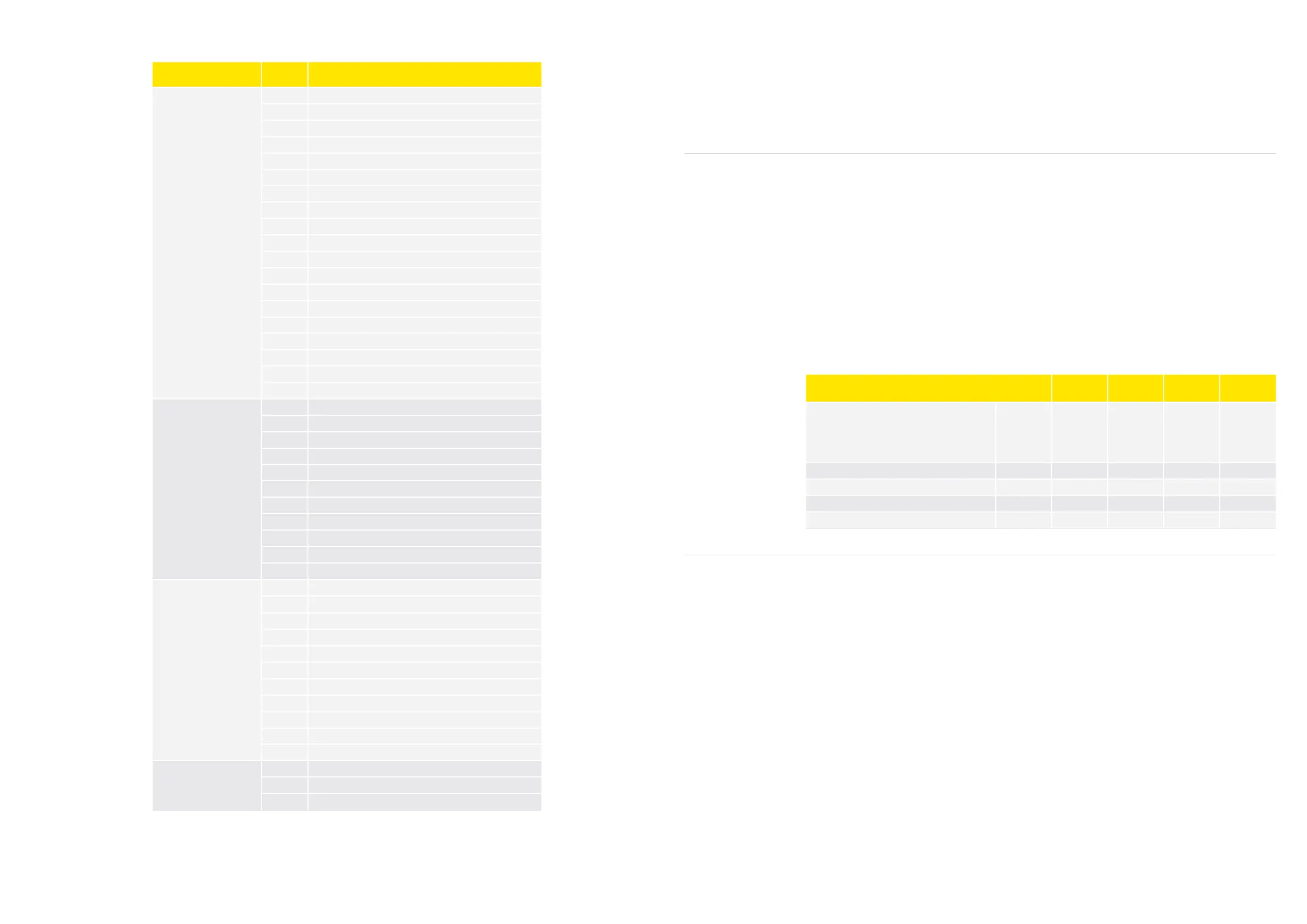
Alarm Groups Code Name
Group 1
System-Related Errors
E81 E81 Motor 1 speed temporarily too high
E82 E82 Motor 1 speed temporarily too low
E81 E81 Motor 2 speed temporarily too high
E82 E82 Motor 2 speed temporarily too low
E81 E81 Motor 3 speed temporarily too high
E82 E82 Motor 3 speed temporarily too low
E92 E92 PCB high temperature stop
E93 E93 Supply voltage failure
E95 E95 Supply voltage frequency failure
E96 E96 PCB 12V failure
E99 E99 Inverter 2 temperature critical
E97 E97 Inverter 3 temperature critical
Err Err No display communication
E54 E54 SAE1 Comm fail
E55 E55 SAE2 Comm fail
E56 E56 SAE3 Comm fail
E73 E73 PCB 2 Temperature critical
E74 E74 PCB 3 Temperature critical
E92 E92 Inverter high temperature stop
Group 2
Sensor Errors
E21 E21 Evaporator temperature too high
E37 E37 Condenser fan temperature stop
E43 E43 Low temperature alarm
E20 E20 High temperature alarm
E60 E60 Temperature logger alarm temperature reached
E24 S1 Sensor error
E25 S2 Sensor error
E27 S4 Sensor error
E26 S3 Sensor error
E57 E57 AIO Min. voltage failure
E58 E58 AIO Max. voltage failure
Group 3
Electronic Faults
UHR UHR Check clock settings
UHR UHR Oscillator for real time clock failure
E70 E70 Modbus failure
E70 E70 EKC failure
E70 E70 Motor 1 voltage failure
E71 E71 Motor 2 voltage failure
E72 E72 Motor 3 voltage failure
E70 E70 Defrost illegal state
E70 E70 Defrost illegal state
E70 Main application control state is illegal
E70 E70 Defrost scheduler state is illegal
Group 4
Motor Faults
E80 E80 Motor 1 error
E80 E80 Motor 2 error
E80 E80 Motor 3 error
 Loading...