Page 18 / 19
3
USER
INTERFACES
The different parameters of the controller
can be accessed via the local display or via
the Modbus. In this section, only the local
display interface will be described.
3.1.
Display
The display performs the following functions:
>
Daily operation of the cooling appliance
>
Readout of measurements and status of the refrigeration system, actual temperature, alarms
>
Defrost activation
>
Start and stop of appliance
>
Setting of parameters
>
Reset of alarms
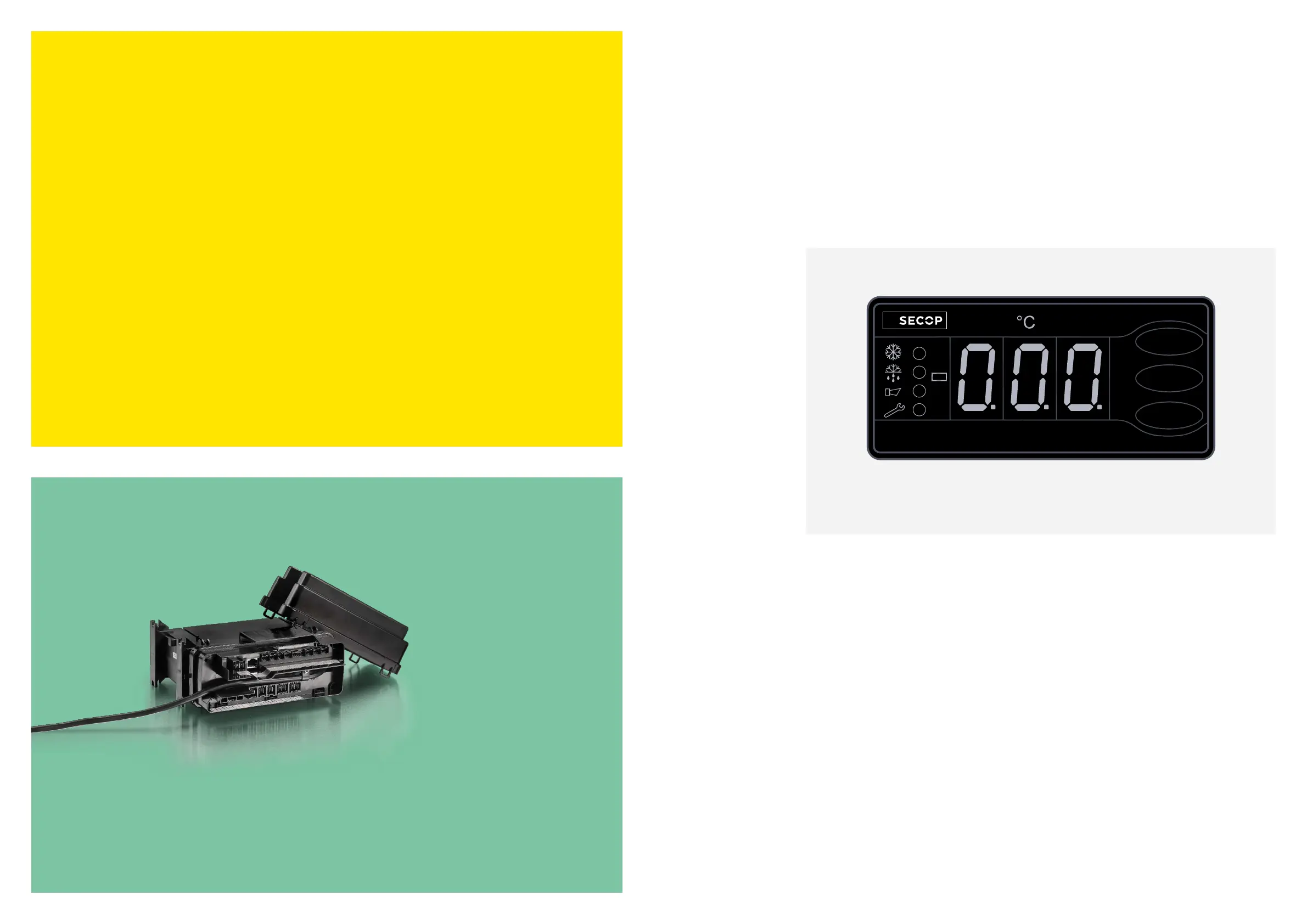
The display has the following layout:
Left are 4 status LEDs with the following functions (from top down):
1) LED 1: Compressor Run Status (unless defrost)
2) LED 2: Defrost, Melt, Case Cleaning
3) LED 3: Alarm
4) LED 4: Editing Mode
>
One minus sign
>
3 seven segment LEDs (1,2,3) with one decimal dot between LED segment 2 and 3
>
3 push buttons with the following names (from top down):
top button, middle button, bottom button



 To Next Page