XT Controllers for NLV-CN Compressors
Page 12 / 13
2.5
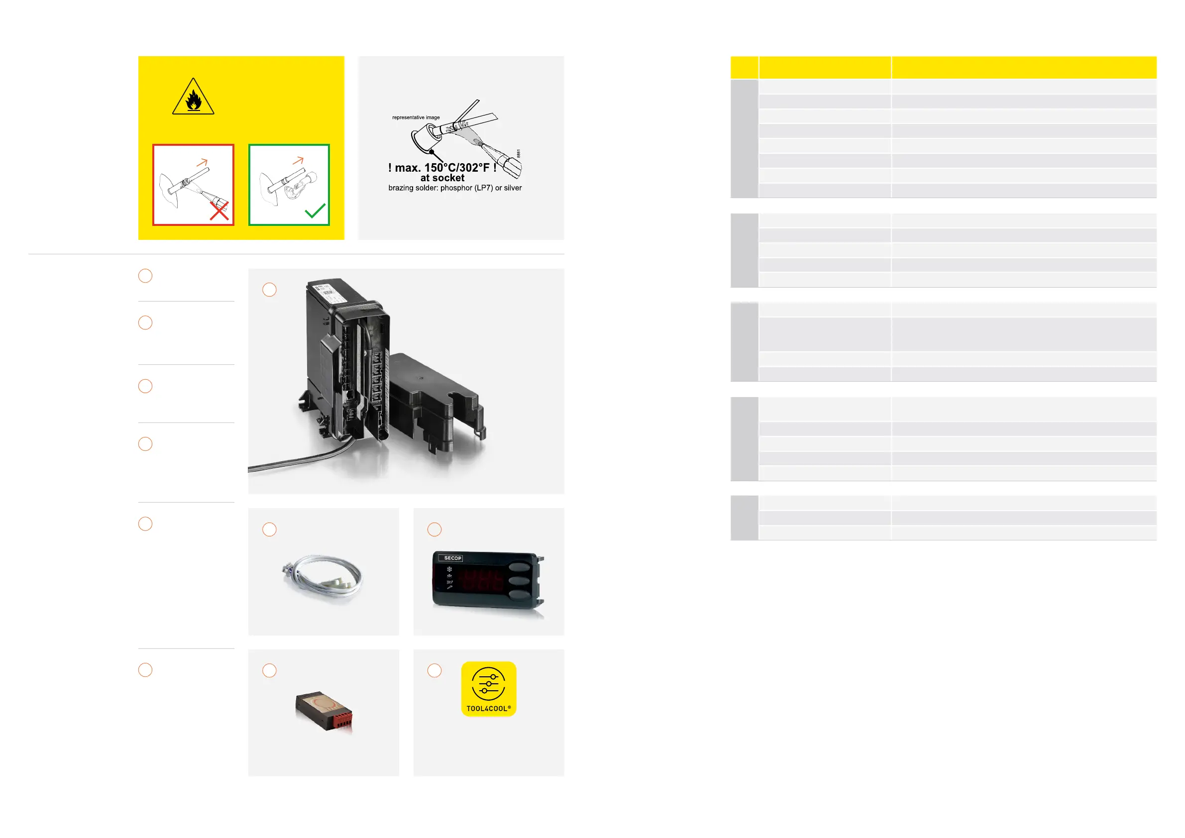
Brazing:
Warning!
Brazing on Suction Connectors
(Direct Intake)
Refer to Product Bulletin:
Brazing on Suction Connectors
(Compressors with Direct Suction Intake)
R290
To remove a compressor
from a system, the tubes
must be cut.
Never use a torch to
remove brazed tubes.
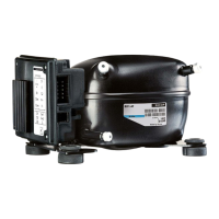
2.6.
Checklist
Software Download
Tool4Cool
®
Flexible Control Settings
www.secop.com/tool4cool
32
4 5
Secop 105N4866
controller
Service product
key for controller:
- On request -
NTC temperature
sensor
(color-coded)
Display
CRA 200, 172
or 162 cable
must be ordered
separately)
RS485 to USB
gateway
>
Gateway
>
USB power
supply
>
DSUB-9/RJ45
adaptor
>
RJ45 Ethernet
patch cable
Tool4Cool
®
LabEdition
software
1
!
2
3
4
5
1
2.7.
Electrical Ratings
Electronic unit 105N4866
Power supply
Nominal voltage 100–240 V AC
Minimum operating voltage 80 V AC
Minimum starting voltage 180 V AC
Maximum voltage 270 V AC
Frequency 50–60 Hz
Max power input 1,000 W
Power factor corrector Yes, active, PF ≥ 0.95
Motor cable length 680±20 mm / 26.0–27.6 in.
Environment
IP class IP43
Humidity 30–90% rH
Maximum operating temperature 50°C / 120°F
Minimum operating temperature 0°C / 32°F
Storage temperature -30 to 70°C / -22°F to 158°F
Approvals/Safety
Compressor protection Software protection + internal in compressor
Safety Approval
UL60335-2-34 with Annex AA
EN60335-2-34 with Annex AA
CB, CCC
EMC conformity According to 2014/35/EC
RoHs conformity 2011/65/EU
Speed control
Frequency input
5–12 V, max. 8 mA, 0–200 Hz
Galvanic isolated, short and reverse protected
AEO thermostat input (Lsw) 80–264 VAC, non-isolated
AEO defrost input (Def) 80–264 VAC, non-isolated
RX/TX interface (DWI) 5–12 V, max. 8 mA, 600 baud galvanic isolated
Single wire interface (SWI) Modbus communication port, 9600 baud galvanic isolated
Relays
Max. individual load RL1–RL7 8A resistive. 30,000 cycles
Max. total load RL1–RL7 16A resistive
Max. load RL8 3A resistive