XT Controllers for NLV-CN Compressors
Page 52 / 53
4.22.
Gearbox
Large appliances in the food retail and food service sector use multiple compressor cycles to gain more
cooling capacity. The reasons are the 150 g propane limitation and a better temperature control.
The multipurpose compressor control function can be used to manage up to three compressors in a
master-client system. Where the master is an extended 2nd gen. controller with application board and the
clients are second generation multipurpose controller.
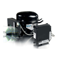
Single V-speed compressor
>
The cabinet is equipped with one V-speed compressor
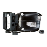
Multiple V-speed compressors
>
Only variable speed can be connected as extension compressors.
>
The main compressor is the direct controlled compressor by default (Master).
>
The first external compressor has the Modbus address 1 by default (Client 1).
>
The second external compressor has the Modbus address 2 (Need to be set in Tool4Cool
®
).
Functional description:
The control of the compressor is implemented as follows:
>
If one compressor is selected the input capacity is normalized to a maximum of 100%.
• If two compressors are selected, the input capacity is normalized to 200%.
• If three compressors are selected, the input capacity is normalized to 300%.
>
Default values are calculated for a compressor with speed range from 2000 to 4500 rpm.
• 100% capacity equals 4500 rpm.
>
When the requested capacity is below compressor capacity for starting PWM control (g07) for a given
compressor, it will stop.
>
When the requested capacity is below compressor capacity for starting speed control (g08) for a given
compressor, it will be cycled to on/off.
• The runtime is determined by the capacity need.
• If the minimum capacity of the compressor is higher than the value given by g08, the min
compressor capacity is used.
>
If the capacity is below g08 * g01, no compressor is running at a speed higher than g08.
Master Controller
Cusomized
AI01
S1+S2
Client 1
Multi Purpose
Client 2
Multi Purpose
Interface description:
The cooling capacity control is possible in two
ways:
>
Temperature control by internal PID regulator
(temperature sensors S1 and S2)
>
Temperature control by external analog signal
(AIO)
• The input voltage is from 0V to 5V
>
The cooling capacity control strategy is
selectable via the parameter CC-Control-Mode
(g09)
Speed control of the external client compressors
is managed by the DIO2 output with single-wire
interface (Modbus protocol).
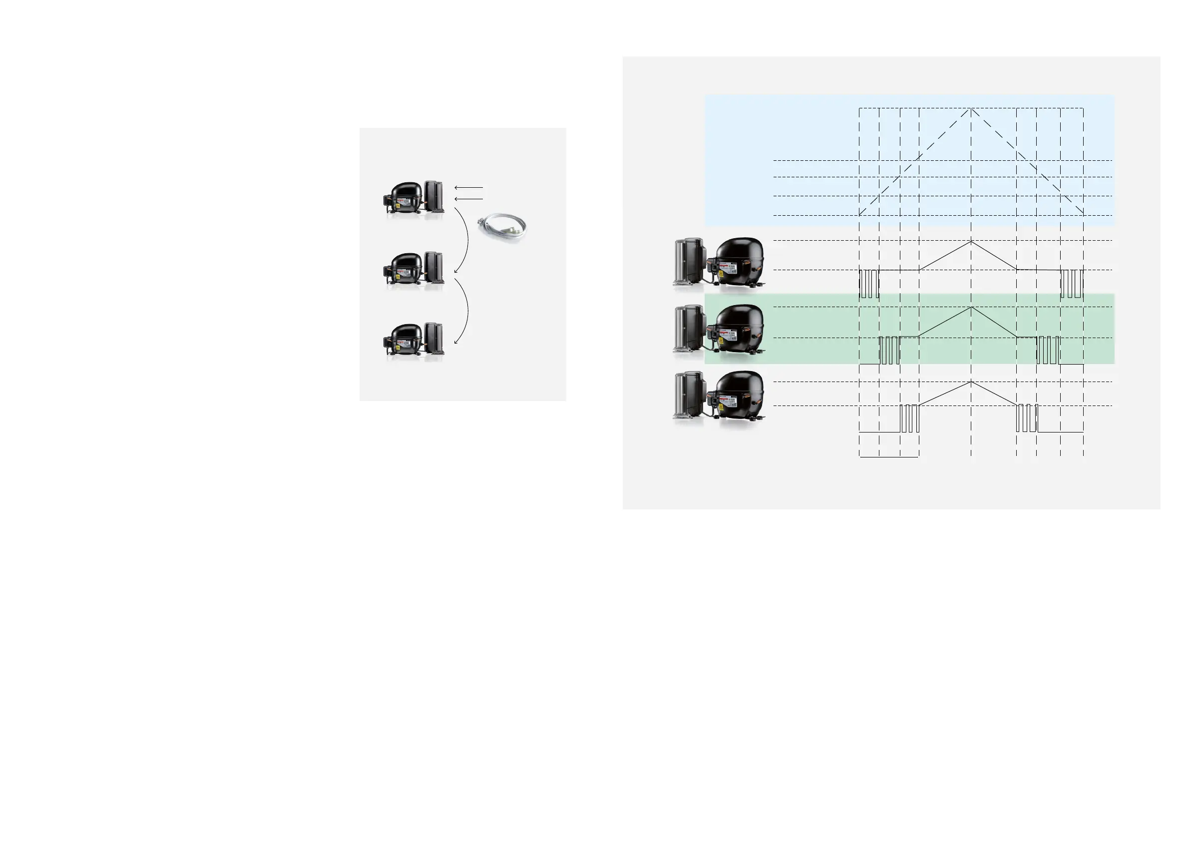
The gearbox is configurable for the following
compressor combinations.
The combination can be selectable via parameter
Number of Compressors (g01).
300% for 3 compressors
135%
90%
45%
0%
Min speed
Max speed
Min speed
Max speed
Min speed
Max speed
Capacity
>
It is possible to distribute the run time between the compressors
• If the runtime of the main compressor exceeds the swap time (g06), the compressors swap priority.
The compressors will then swap priority again when the new main compressor exceeds the swap
time (g06)
>
If the parameter CC-Control-Mode (g09) is set to 0 (internal temperature control (PID)):
The speed control is depending on the cooling capacity demand from the PID regulator
>
The compressors start separately one by one with a compressor start delay (g14)
• The start delay only applies to compressors 2 and 3.
>
The parameter Compressor Period time (g05) gives the cycle time of the PWM mode.
• The Compressor Period time (g05) may be increased if g03 or g04 cannot be respected.
>
The compressor run time control is performed as follows for each compressor:
 Loading...