XT Controllers for NLV-CN Compressors
Page 54 / 55
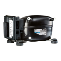
Run request
Run actual
g04/g08 Min Run Time g03/g07 Min Stop Time
>
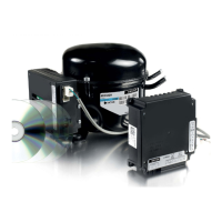
If the parameter CC-Control-Mode (g09) is set to 1 or 2 (external analog signal (AIO)).
The speed control is as shown below:
>
If the parameter CC-Control-Mode (g09) is set to 1 or 2 (external analog signal (AIO)):
• If the AIO input voltage is below the fallback voltage (AC10) or above the maximum voltage (AC15)
the compressors are running at emergency capacity (n21).
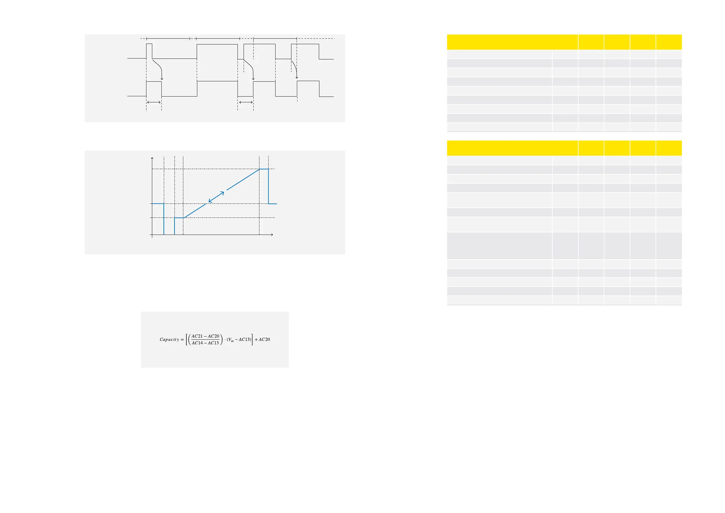
• The compressor speed is calculated by using the following equation:
Capacity
Voltage and Motor Speed
[%]
AC21
AC20
0
0
N21
Parameter Function Code Min. Max.
Default
Setting
Unit
Analog Input Signal AC01 V
Requested Motor Speed AC02 RPM
Fallback Voltage AC10 0 5,8 0,3 V
Minimum Voltage AC12 0 5,8 0,5 V
Voltage Ramp Start AC13 0 5,8 1 V
Voltage Ramp End AC14 0 5,8 5 V
Maximum Voltage AC15 0 5,8 5,5 V
Minimum Capacity AC20 0 100 0 %
Maximum Normal Capacity AC21 0 100 100 %
Parameter Function Code Min. Max.
Default
Setting
Unit
Number of Compressors g01 1 3 1 -
Compressor Minimum Stop time g03 1 240 90
sec.
Compressor Minimum Run time g04 1 240 30
sec.
Compressor Period time g05 5 60 30
min.
Compressor Swap Time
0 = None
g06 0 60 1 day
Compressor Capacity for starting PWM control g07 1 100 1 %
Compressor Capacity for starting speed con-
trol
g08 20 100 45 %
CC-Control-Mode
0 = Internal temperature control (PID)
1 = External analog signal (AIO1)
2 = External analog signal (AIO2)
g09 0 2 0 -
Capacity compressor 1 g10 0 100 RO %
Capacity compressor 2 g11 0 100 RO %
Capacity compressor 3 g12 0 100 RO %
Actual main compressor/swapped g13 0 3 RO -
Compressor Start Delay g14 0 60 5
sec.
 Loading...