XT Controllers for NLV-CN Compressors
Page 72 / 73
8.1.1.
Input Power
Name Pin Type Specification
Protective Earth
PE
2x Faston 6.3 mm × 0.8 mm
PE
Neutral
N Faston 6.3 mm × 0.8 mm
Neutral and Phase
N
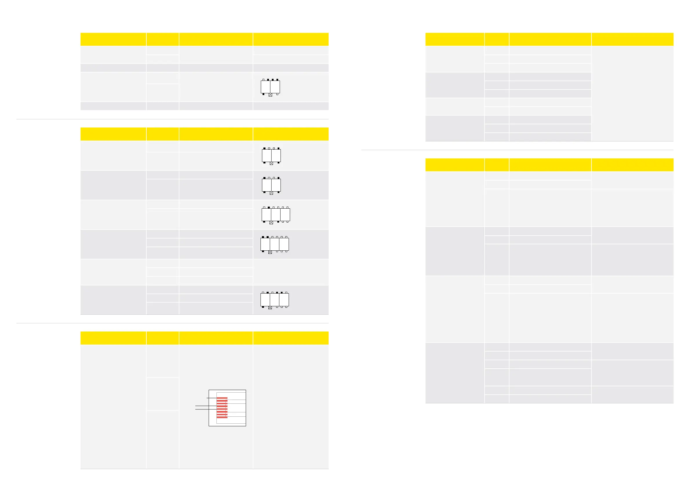
2-Pole RAST 5 connector
The coding scheme shows posi-
tion of keying and locking latches.
Black means the key is present.
P
1
K
2
1a 1b 2a 2b
1c 2d
L1
Phase
L1 Faston 6.3 mm × 0.8 mm 16A Fuse
Name Pin Type Specification
RL 1
1 Live switched, N.O.
P
1
K
2
1a 1b 2a 2b
1c 2d
2 Neutral
RL 2
1 Live switched, N.O.
P
1
K
2
1a 1b 2a 2b
1c 2d
2 Neutral
RL 3
1 Live switched, N.O.
P
1
K
2 3
1a 1b 2a 2b 3a 3b
1c 2d 3a 3b
2 Neutral
RL 4
RL 5
1 RL4 output, Live switched, N.O.
P
1
K
2 3
1a 1b 2a 2b 3a 3b
1c 2d 3a 3b
2 RL5 output, Live switched, N.O.
3 Neutral
RL 6
RL 7
1 RL6 output, Live switched, N.O.
2 RL7 output, Live switched, N.O.
3 Neutral
RL 8
1 N.C.
1
K
P
2 3
1a 1b 2a 2b 3a 3b
1c 2d 3a 3b
2 N.O.
3 Base pin
Name Pin Type Specification
MODBUS
RTU
4/D1
1
8
Standard: IEA485
Maximum nodes:
With RC termination
100
With Resistor termination
up to 32
Cable max. length:
1,000 m
Maximum stub no. and length
30/1 m
Termination:
Resistor 150 Ω (30 nodes)
Recommended RC series:
120 Ω, 1nF
Installation must be in accordance
to “standard modbus.org” with
RJ45 plugs and CAT5
5/D0
8/Common
8.1.2.
Relays
8.1.3.
Modbus
Name Pin Type Specification
S1
1 GND
Measurement range: -55 to 85°C
Sensor Characteristics:
Nominal Resistance at 0°C: 16.3 kΩ
Nominal Resistance at 25°C: 5.0 kΩ
Nominal resistance tolerance: ±2%
B value: 3980 K
B value condition: B25/100
B value tolerance: ±1.5%
2 Not connected
3 Analogue input
S2
1 GND
2 Not connected
3 Analogue input
S3
1 GND
2 Analogue input
S4
1 GND
2 Not Connected
3 Analogue input
8.1.5.
Analog and Digital IOs
8.1.4.
Temperature Sensors
Name Pin Type Specification
DIO1
1 GND
10-12 V DC
2 V supply
3 Digital I/O
Digital output:
“Open collector”
Internal pull-up resistor to V supply:
0 kΩ
Signal voltage range:
5–12 Vpp
DIO2
1 GND
10–12 V DC
2 V supply
3 Digital I/O
Digital output “Open collector”
Internal pull-up resistor to V supply
10 kkΩ
Signal voltage range:
5–12 Vpp
Display
(DIO3)
1 GND
10-12V DC
2 V supply
3
Single-wire com signal
(SWI)
Internal pull-up resistor to V supply
10 kΩ
Signal voltage range:
5–12 Vpp
Max current sourcing:
20 mA
Half-duplex single wire, baud rate:
1200–9600
AIO1
1 GND
10–12 V DC
2 V supply
3 Analog/Digital input Analog signal range:
0–5 V
Input impedance
>10 kΩ
4 Analog/Digital input
5 Analog output
Not enabled yet
6 Analog output
Find more details in chapter: Hardware Interface description/Installation