XT Controllers for NLV-CN Compressors
Page 62 / 63
The max total load of RL1 to RL7 is 8 amps, which must be shared for these 7 relays. Please see the
technical data for the controller.
The relay RL8 is galvanic isolated from the rest of the electronics and can be used in a separate alarm
circuit or as a changeover relay in certain applications. The max total load of RL8 is 2 amps
Relay settings must be done for each application. With the Relay configuration parameters L01 to L08,
each of the 8 relays can be defined as follows:
Error Type Description
0 Always Off No control functions attached to the relay.
1 Always On
The relay will be activated as soon as the controller is
connected to the mains supply.
2 On during operation
The relay will be activated as soon as the controller is en-
ergized and has left stopped mode.
3 On during stopped
The relay will be activated as long as the controller is en-
ergized and in the stopped mode.
4 Follow Compressor
The relay will stay On as long as the compressor is run-
ning.
5 Condenser Fan On The relay is controlled by the condenser control function.
6 Evaporator Fan On The relay is controlled by the evaporator control function.
7 Defrost
The relay is attached to the defrost control algorithm. The
relay will be On, when defrosting heat is activated. This
can be an electrical heater or a hot gas valve.
8 Drain Heater
The relay is controlling the drain heater, which can be en-
ergized prior to, during, and after a defrosting.
9 Cnd Fan High Speed
The relay is controlled by the condenser control function
and activated when the fan must run at high speed. For
dual speed fans only.
10 Rail Heater function The relay is controlled by the rail heater control function.
11 Blind curtain
It’s possible to connect a night blind or curtain to the relay
output, which is controlled by the night blind function.
12 Light Relay will be controlled by the light function.
13 Not used
14 Evap Fan High Speed
The relay is controlled by the evaporator control function
and activated when the fan is run at high speed. For dual
speed fans only.
15 Alarm
The relay is used for local alarm indication. The relay will
be activated as soon as the controller is energized and
no alarms are active. If a galvanic separated alarm is re-
quired, the relay RL8 must be used.
16
Temperature logger
alarm relay
The relay is used for temperature logger alarm indication.
17 Do not use Not in use yet.
18 Control timer
The relay will follow the status of the control timer. The
relay will be active, when the control timer is active.
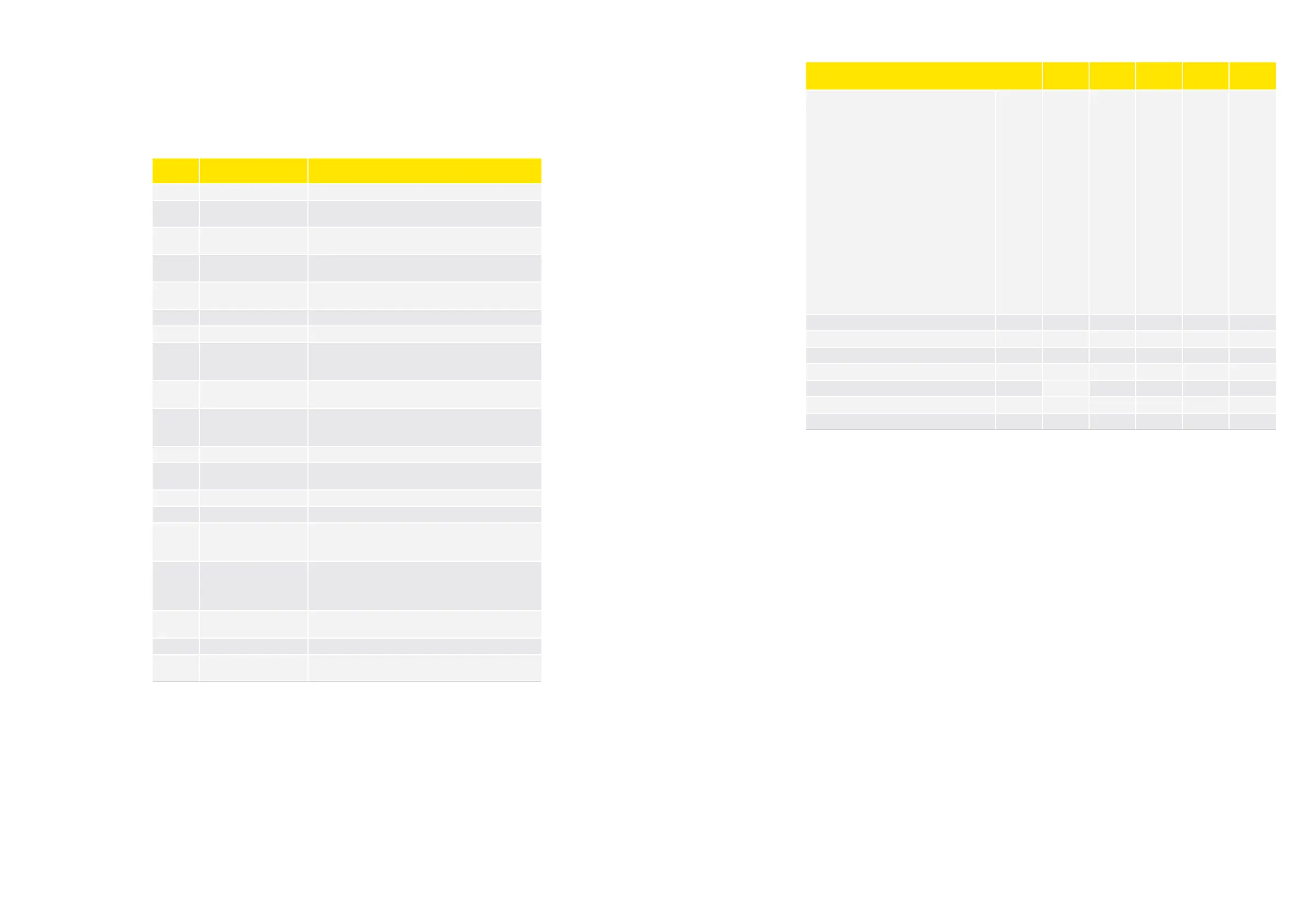
Parameter Function Code
Multi
Apps
Min. Max.
Default
Setting
Unit
Relay 1 configuration
0=Always Off
1=Always On
2=On during operation
3=On during stopped
4=Follows compressor
5=Condenser fan
6=Evaporator fan
7=Defrost
8=Drain heater
9=Condenser fan high speed
10=Rail heater function
11=Blind relay
12=Light relay
13=Not used
14=Evaporator fan high speed
15=Alarm relay
16=Temperature logger alarm relay
17=Do not use
18=Control timer
L01 x 0 18 4 -
Relay 2 configuration L02 x 0 18 0 -
Relay 3 configuration L03 x 0 18 13 -
Relay 4 configuration L04 x 0 18 14 -
Relay 5 configuration L05 x 0 18 0 -
Relay 6 configuration L06 x 0 18 0 -
Relay 7 configuration L07 x 0 18 0 -
Relay 8 configuration L08 x 0 18 15 -