XT Controllers for NLV-CN Compressors
Page 68 / 69
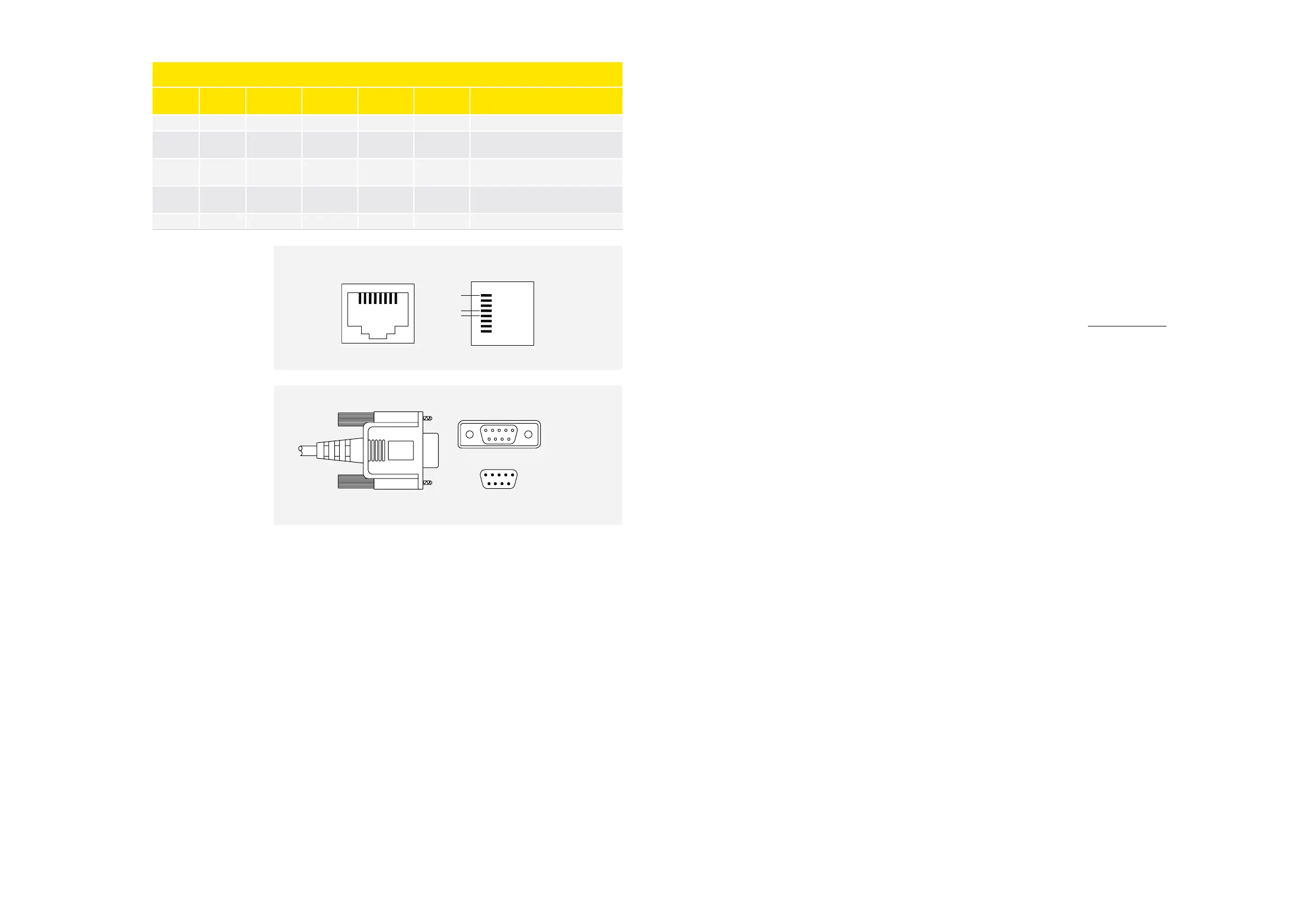
Pin Assignment for RJ-
45 and D-Sub
RJ-45 Jack for Single-
Pair Communication
Device Side – Female
Connector
2W-Modbus RJ45 and 9-Pin D-Shell Pinouts
Pin on
RJ45
Pin on
D9-Shell
Level of Re-
quirement
IDv Circuit ITr Circuit
EIA/TIA 485
Name
Description for IDv
3 3 Optional PMC - - Port Mode Control
4 5 Required Df D1 B/B’
Transceiver terminal 1.V1 voltage
(V1>V0 for binary 1 (Off) stage)
5 9 Required D0 D0 A/A’
Transceiver terminal 0, V0 voltage
(V0 > V1 for binary 0 (ON) state)
7 2
Recom-
mended
VP - - Positive 5…24 V D.C. Power supply
8 1 Required Common Common C/C’ Signal and power supply common
D1 - pin 5
D0 - pin 9
wiring side
1 2 3 4 5
8752
Common
D0
D1
1
1
8
8
The following systems can be connected to the Modbus:
>
ADAP-KOOL
®
– Danfoss supermarket monitoring system
>
Master functions:
• Night offset
• Blind
• Clock synchronization
• Alarm limit offset
• Dew point control
>
Tool4Cool
®
– Secop tool for adjusting and servicing of variable speed compressor products
The possibility of errors in the installation is very limited when using standard computer network
equipment for the Modbus. A safely running bus is ensured with BIAS resistors (inside the bus masters)
and the correct termination. Bigger networks require a proper installation of common lines and shielded
cables.
For more information please refer to "Technical Resources" on: www.modbus.org