Doc. No.: A05280692 Rev. AE ECO: 13200 Date: 11/04/2019
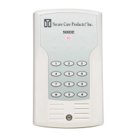
KinderGUARD® ID Exit Panel
NOTE: Not all ID Exit Panels will have every feature set or all components
populated. Refer to specific Part Number or Exit Panel model name for
available feature sets.
The ID Exit Panel is a microprocessor-based unit that recognizes pulse signals sent from Secure Care Products, Inc.
Transmitters. This perimeter control panel can allow for traffic to pass normally, but can engage an optional magnetic
lock when a Secure Care transmitter is within detection range. The ID Exit Panel should create an audible and visual
alarm when a transmitter is in detection range and the door is open. The system can trigger an alarm at a PC based Secure
Care Software graphic annunciator in a specified remote location. The escort feature allows infants wearing Secure Care
Products, Inc. Transmitters to be escorted without alarm when an authorized, user programmable, four digit code is
entered. The anti-tailgate feature should immediately re-arm the system when the door has closed to prevent an
unauthorized exit. The PM feature allows the system to lock or alarm for exit/entry during specified time periods.
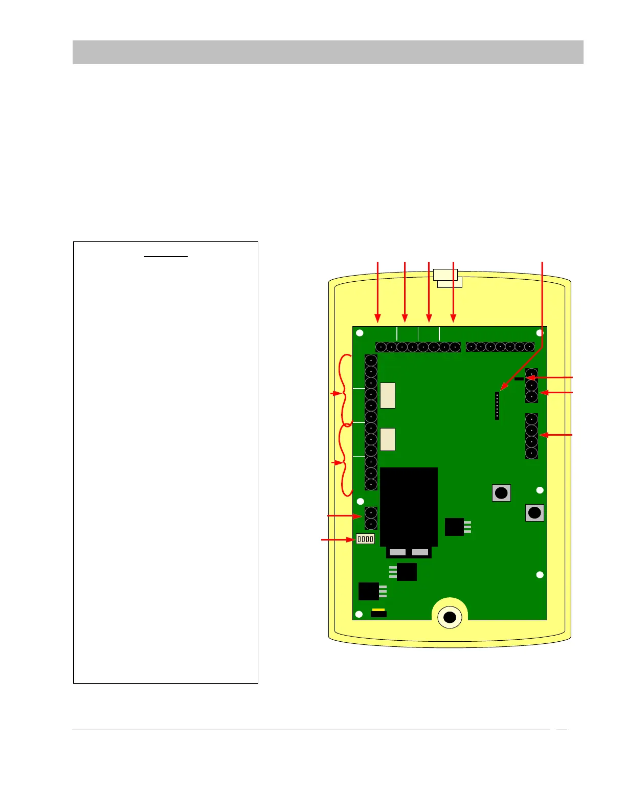
Figure 8-1 Rear View of ID Exit Panel
SECTION 8 SYSTEM COMPONENT DESCRIPTIONS
FIRE
PUSH
DOOR
EGRESS
LOCK
AUX
CAN
L
CANH
GND
SECURE CARE PRODUCTS
AUX
LOCK
- +
NO C NC
NO C NC
NO C NC
NO C NC
- +
KEYPAD
O N
1 2 3 4
1 2 3 4 5 6 7
1 2 3 4
2 3 41
6
7
8
9
5
11
10
12
1- Power
2- Mute
3-Loud/Soft
4- Not Used
LEGEND
1. Electromagnetic lock Delayed Egress
connection
2. Normally Closed door contact
connection
3. Momentary Push Button or Non-
latching Key Switch
4. Fire alarm Normally Open dry alarm
relay connection (field selectable)
5. Controlled area network (CAN)
connection
6. Remote Keypad connection (seven
pin)
7. Electromagnetic lock relays , one and
two connections
8. Auxiliary relays (one and two
connections)
9. 12-15VDC power input connections.
Use plug-in power supply or central
power supply.
- 10. CAN Bus termination jumper
11. Ext. Receiver connections
12. Dipswitch settings


 To Next Page