Doc. No.: A05280692 Rev. AE ECO: 13200 Date: 11/04/2019
ID Exit Panel to XIU Connections
The ID Exit Panel can be connected to a PC based Secure Care Software graphical annunciator thru an XIU. This is done
by connecting the ID Exits to the XIU CAN bus interface. Wire the ID Exit Panels in daisy chain fashion and connect to
the XIU CAN bus. The Secure Care Software will provide a specific location of a device in alarm as identified by the
unique field device ID code set for that device. The XIU receives a CAN message from field devices during alarm, alert,
and supervisory events. If each field device is wired properly to the XIU, the initial alarm trigger will provide a pre-
programmed alarm message or supervisory signal on the computer monitor. Up to 95 total ID Exit Panels can be
connected to an XIU. Each device will require its own uniquely programmed addressable ID. Please refer to Section 10
for programming instructions for the Exit Panel.
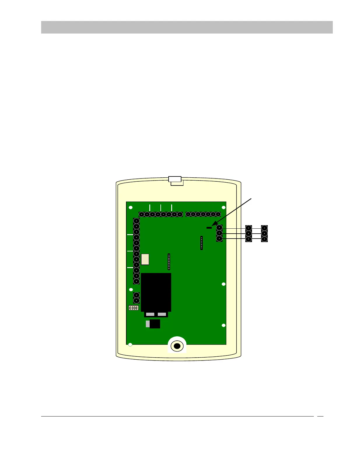
Keeping all the HIGH, LOW and GND color coded connections consistent, terminate wires as outlined in Figure 9-6. The
120 Ohm resistor (jumper) located next to the CAN interface screw terminal must be on both pins at each end of the loop.
FIRE
PUSH
DOOR
EGRESS
AUX
CANL CANH GND
SECURE CARE
PRODUCTS
LOCK
- +
NO C NC
- +
KEYPAD
O N
1 2 3 4
1 2
3
4 5
6 7
1) POWER
2) NOT USED
3) NOT USED
4) NOT USED
LOCK
NO C NC
AUX
NO C NC
NO C NC
CANLCANHGND
FROM ID EXIT
PANEL
RESISTOR /
JUMPER
GND
CAN H
CAN L
XIU
Figure 9-7 ID Exit Panel to XIU Connections
SECTION 9 INSTALLATION AND CONNECTIONS


 To Next Page