Doc. No.: A05280692 Rev. AE ECO: 13200 Date: 11/04/2019
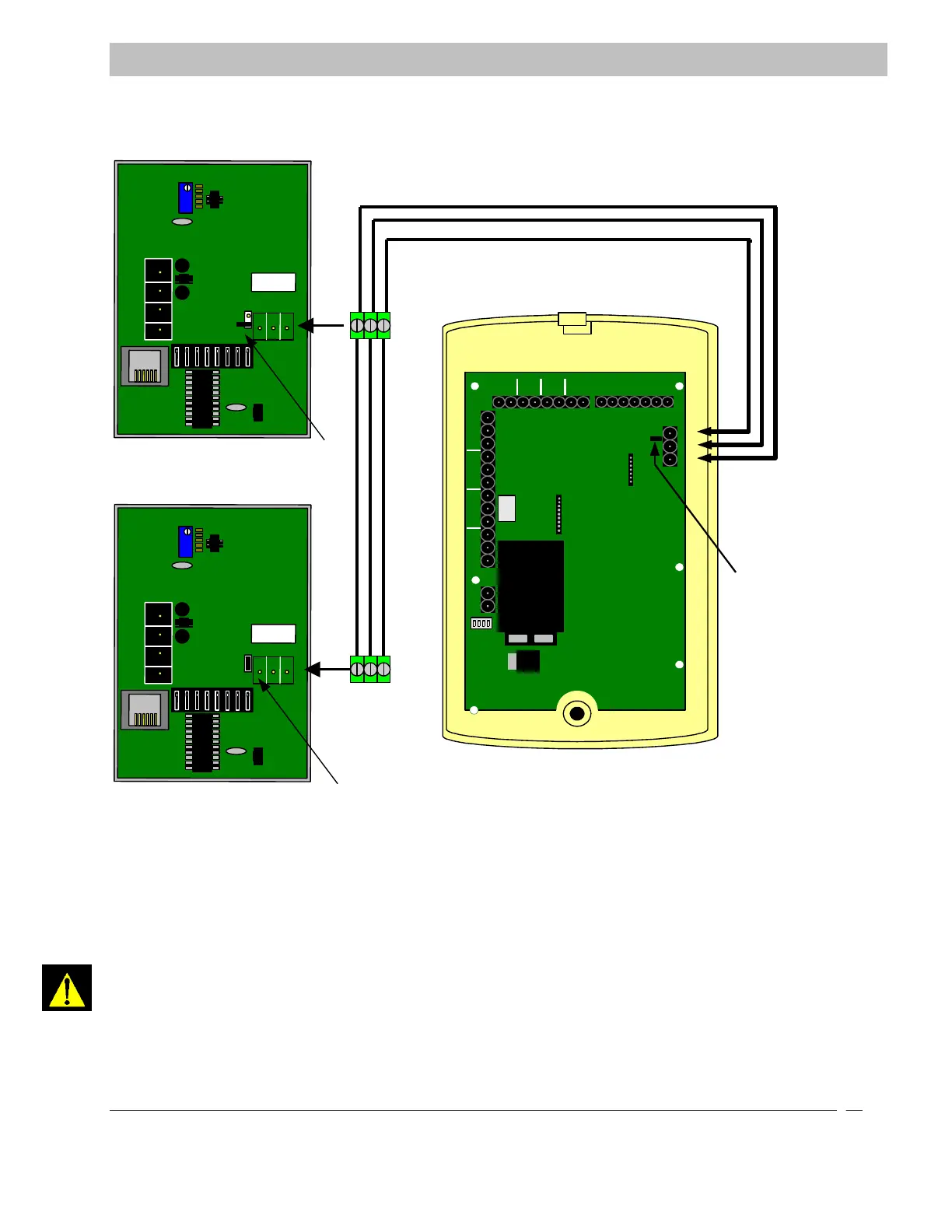
Cutband Receiver Data Connection
1 2 3 4
1
2
3
4
5
6
7
8
ON
Secure Care Products, Inc
12v DC ONLY!
REV
P03290012 REV1
12v DC ONLY!
1
2
3
4
5
6
7
8
ON
Secure Care Products, Inc
12v DC ONLY!
P03290012 REV1
12v DC ONLY!
REV
G H L
G H L
G H L
+
_
+
_
+
_
+
_
JUMPER
ON
JUMPER
ON
JUMPER
OFF
FIRE
PUSH
DOOR
EGRESS
AUX
CA
NL
CANHGND
SECURE CARE
PRODUCTS
LOCK
- +
NO C NC
- +
KEYPAD
O
N
1 2 3 4
1 2 3 4 5 6 7
1) POWER
2) NOT USED
3) NOT USED
4) NOT USED
LOCK
NO C NC
AUX
NO C NC
NO C NC
XIU
Figure 9-19 Cutband Receiver Data Connection
Connect all HIGH’s, LOW’s and GROUND’s. All three conductors must be connected. All Cutband Receivers must
have a unique ID. Follow the numbering sequence in Section 9, “Setting the Proper Cutband Receiver ID Code” for
setting the Cutband Receiver’s unique ID numbers. The Cutband Receiver uses a binary numbering sequence. Use
binary numbers between 1 and 95.
Secure Care strongly recommends that all wiring used to install Secure Care equipment be run at least
18 inches from all other wiring and not be installed inside metal conduit. It is also strongly
recommended to not utilize cable trays used in networking installations and to keep the wires off of
ceiling grids. If the wiring is installed in any of these manners it could cause undesired induction of
Radio Frequency (RF) interference with our system.
SECTION 9 INSTALLATION AND CONNECTIONS


 To Next Page