Doc. No.: A05280692 Rev. AE ECO: 13200 Date: 11/04/2019
Antenna Selection
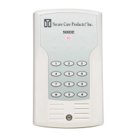
Each ID Exit Panel has an integrated antenna system in the unit. However, due to special requirements of certain
installations, you may be inclined to add an external antenna to the ID Exit Panel. In order to choose the external antenna
solely for coverage or choose both, the following steps will allow you to choose the proper setup for your installation
needs.
To change the selection of antennas
1. Enter *567 or currently programmed Secondary Code, Enter *5 and hold the 5.
One beep = board antenna is active
Two beeps = remote antenna(s) is active
Three beeps = both the on board antenna and remote antenna(s) are active
Four beeps = neither antennas are active
To Enable or Disable the Signal LED on the ID Exit Panel Factory Default LED Enabled
Enter *567*6 and hold the 6 until beep is heard
Two beeps = Signal LED Disabled
One beep = Signal LED Enabled
Antenna Range Adjustment
Each door system installation will be unique in many ways. Consider all of the local environmental factors of construction
around the system location; the types of materials used, the construction methods used, and amount of foot traffic around
and through the door area. Each system will require tuning for the required coverage at each location independently.
Every panel ships from Secure Care Products with a threshold value of 200. The following steps will guide you during
the adjustment.
1. Enter *567 (or currently programmed secondary code) *9876543219
Five beeps indicate that you are in range adjustment mode
2. Enter “1” and the current threshold will be given in a series of beeps.
1-9 beeps indicate its numeric value.
Ten beeps indicate a value of zero.
3. Enter “*” followed by three digits of desired threshold value
Higher the value = shorter range
Lower the value = longer range
4. Enter “0” to select the on board antenna or remote antenna
Four beeps = adjust the remote antenna
Two beeps = adjust the onboard antenna
5. Enter “#” to get out of the range change mode or wait one minute.
Three beeps = end of range adjustment mode.
Testing the CAN Bus
To test the CAN bus connection:
1. Enter *567 *1 and hold the one
One beep = the bus is not connected
Four beeps = communicating to at least one other device.
SECTION 9 PROGRAMMING INSTRUCTIONS SECTION 10 PROGRAMMING INSTRUCTIONS


 To Next Page