Secutron Inc. 25
4 Wiring the MR-2605
4.1 Wiring Specifications
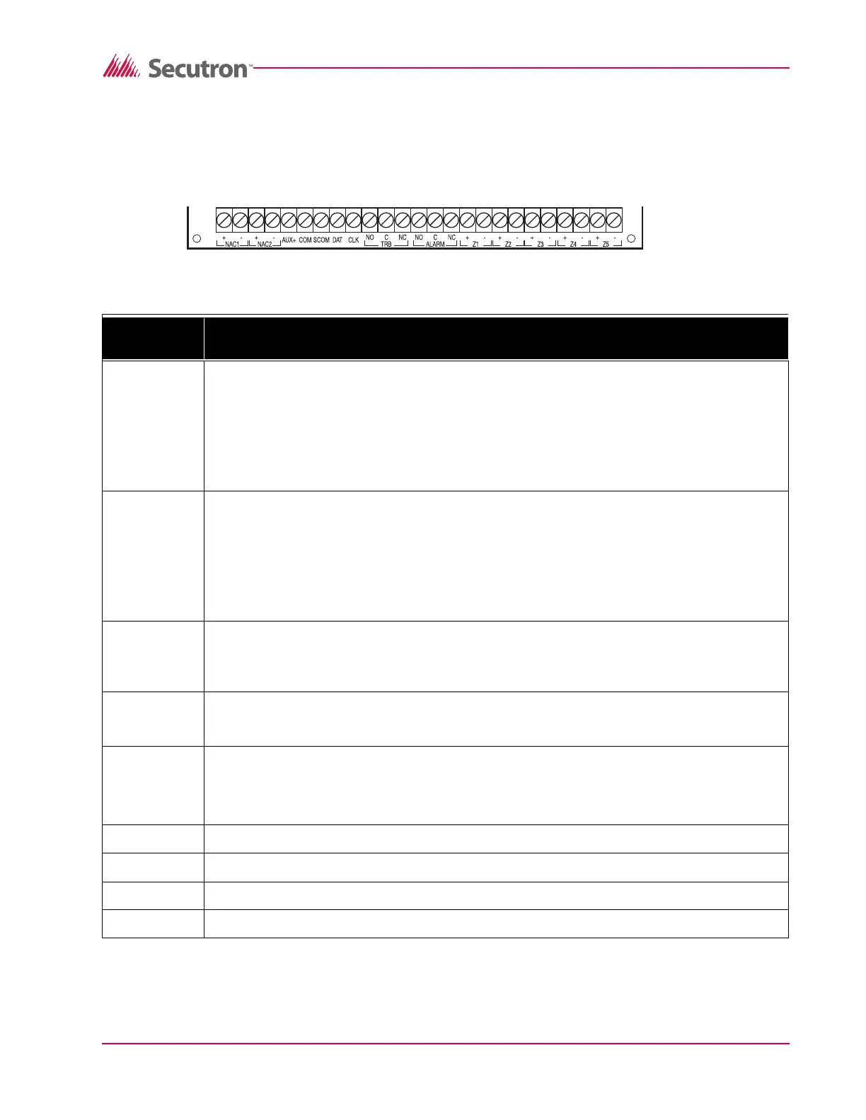
Figure 8 MR-2605 Terminals Descriptions
Te rm in a l
Label
Description
NAC 1
(+, –)
Notification Appliance Circuit # 1
24 V
DC, Full-Wave Rectified voltage, 1.5 Amps max.
Programmable as Steady or Temporal output on alarm.
Supervised for opens, shorts and ground fault.
Power limited.
NAC 2
(+, –)
Notification Appliance Circuit # 2
24 V
DC, Full-Wave Rectified voltage, 1.5 Amps max.
Programmable as Steady or Temporal output on alarm.
Supervised for opens, shorts and ground fault.
Power limited
AUX+ Auxiliary power output
24 V
DC, filtered and regulated, 500 mA max., 400 mV P-P ripple, power limited. Aux power
shorts must be restored by removing all Aux Power loading.
COM Auxiliary common power return, unswitched
24 V
DC, 500 mA max.
SCOM Auxiliary common power return, switched
(open circuit on system reset or on 4-wire smoke detector reset)
24 V
DC, 500 mA max. (Please refer to Appendix A for compatible 4-wire smoke detectors.)
DAT Data line for remote module communications
CLK Clock line for remote module communications
TRB NO Common Trouble relay, Normally Open contact
TRB C Common Trouble relay, Common contact