Secutron Inc. 18
2.6 Module Current Ratings
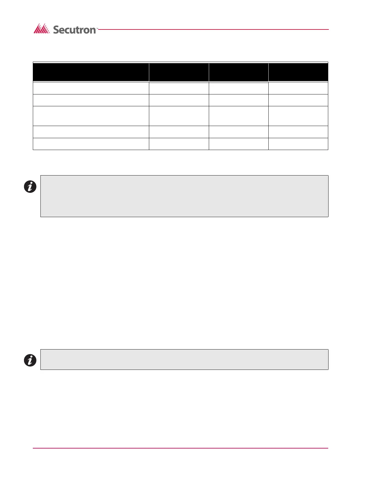
Table 2 Module Current Ratings
2.7 Standby Battery calculation chart
1. All components that draw current from the panel while it is in the ‘standby’ mode (AC OFF)
must be considered for the standby battery calculation. All components that draw current
while in the ‘Alarm’ mode must be considered for the alarm battery calculation.
2. The control panel will always draw the currents as shown in the chart.
3. Typically the alarm current is calculated assuming only one initiating zone is in alarm. If it is
required that more than one zone be considered, add 60 mA per zone in the Alarm column.
Consult the smoke detector manufacture’s installation sheet to determine the standby
current of these devices. Write that number in the ‘current per device’ column then multiply
that number by the number of devices on the zone. Repeat for each zone.
4. Consult the Notification Appliance installation sheet to determine the current draw for each
device connected to the NAC. For each NAC, calculate the total current in alarm and put
that number (mA) in the ‘Alarm’ column.
5. For each added module in the system, multiply the number of modules times the module
‘standby’ and ‘alarm’ currents and write those totals in the ‘standby’ and ‘alarm’ columns.
6. Add up all the current drawn from the AUX+ output in the standby and alarm mode and put
those totals in the ‘standby’ and ‘alarm’ columns.
7. Add up all the currents in the ‘standby’ column and the ‘Alarm’ column.
8. Convert the ‘standby’ and ‘alarm’ currents from mA to Amps. (divide mA by 1000)
Module Standby Current
(mA) DC
Alarm Current (mA)
DC
Max. Alarm Current
(mA) DC
MR-2605 Control panel 130 475* 715
MR-2605-T Remote trouble indicator 15 15 15
MR-2605-AT R.T.I. and remote 5 zone
annunciator
15 20* 40
MR-2806 DACT 45 60 60
MR-2605-R3 Relay module** 0 24 24
Notes: *Current noted assumes ONE initiating zone is in alarm. The “Max. Alarm Current” assumes all
zones are in alarm.
**Values shown are for all relays set for activation on ‘Alarm’. Each relay set for activation on
‘trouble’ is normally energized and on ‘AC fail’ will draw 0 mA.
Note: Each NAC can supply 1.5 Amps max.