Universal Radiographic System
Service Manual
SM-0524R4
10
13. Install the Control Unit on the wall near the Column (refer to
Illustration 3-2).
14. For the Manual version:
a. Install the lower cover of the Control Unit Box. Identify and
separate the cables to be connected to the Control Unit and the
cables to be connected to the Generator Cabinet.
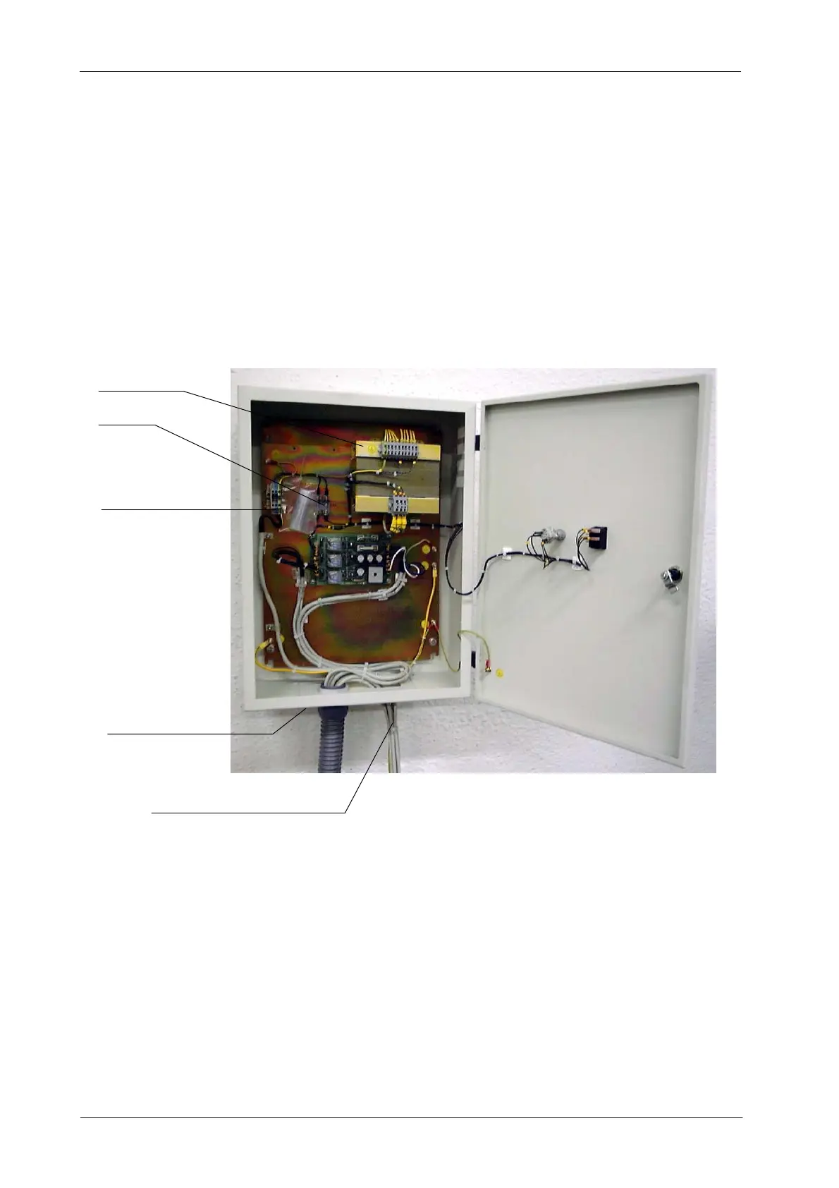
Illustration 3-7
Control Unit Box Connections for Manual Version
TRANSFORMER
CABLES FOR GENERATOR CONNECTIONS
LINE FUSES
POWER LINE CONNECTIONS
LOWER COVER
b. Connect to the Optima Universal Board (A3127--XX) all the wires
from the main harness (GND and wires to TS2 and TS3) (refer to
Interconnections Map I/M-041).
c. Connect to the Generator the cables from the main harness
(Stator, Bucky and ground (GND) cables routed directly from the
Column) (for these connections refer to Interconnections Map
I/M-041 and also to Generator Service Manual).
d. Connect directly the ground cables (GND) from the Column and
Control Unit Box to the Main ground stud (GND) of the Generator.