67
English
Thisashingsequenceindicatesacommunication
errorbetweentheleaderWallboxortheexternal
control system and the corresponding follower
Wallbox.Checkwhetherthebusinstallationwas
performed correctly. Once the fault has been
remedied and a self-test has been performed, the
front illumination lights up white and the charging
processcanberequested.Pleasecontactthe
Hotline if the fault persists.
5.1 Modbus connection
TheWallboxisconnectedtoanexternalcontrol
systemusingatwo-wireRS485bus(half-duplex).
Busparametersused:
• Baud19200bit/sec,
• 8 data bits,
• 1 stop bit,
• 1paritybit(even),
• Leastsignicantbitsentrst(LSBrst).
Only unicast mode is supported as the addressing
mode.
Broadcast mode is not supported.
5.2 Functions supported by the Modbus
protocol
TheWallboxessupportexclusivelythefollowing
functions:
• 03(0x03)ReadHoldingRegister
• 04(0x04)ReadInputRegister
• 06(0x06)WriteHoldingRegister
• 16(0x10)WriteMultipleRegister
The byte sequence is High byte before Low byte
(Motorolaformat).
TheCRCchecksumsequenceisLowbytebefore
Highbyte(Intelformat).
6. Checking load management
Puttheloadmanagementsystemintooperation
afterproperlyinstallingandconguringit.
i
Whencheckingtheloadmanagementsystem,
ensurethatnovehicleisconnectedtoanyWallbox.
• EstablishthepowersupplyfortheWallboxesin
local load management mode, beginning with
theleaderWallbox.
• Establish the power supply for all devices in
externalloadmanagementmode,beginning
withtheexternalcontrolelectronics.
• ThefrontilluminationofeachWallboxlightsup
for 5 minutes and then goes out.
• Load management is now ready for operation.
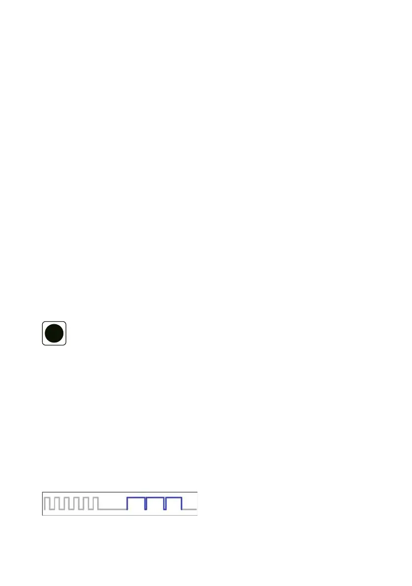
Diagnosisofcommunicationerrorsintheload
management system via the front illumination.
Thefrontilluminationashesintheeventofafault.
Sixbriefwhiteashes.Pause,threelongblueashes.
Pause.
 Loading...