Io
SENSOR
Section 6 SMT-200 Technical
SMT-200 Operations and Technical Manual 2.00/R1
75
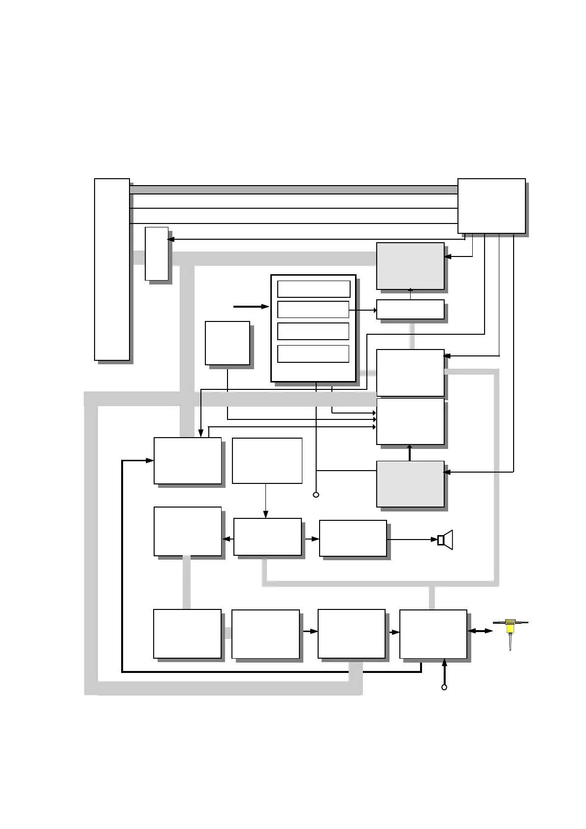
6.4 SMT-200 Main Board block diagram
This section contains a functional description of the SMT-200 main board. The board contains all the
required circuitry to generate the test signals for the geophones and digitise the signals via the A-D
converter. In addition the board has the keypad and LCD display drivers and also the power supply
circuit.
-23V Supply
±15V Supply
+5V Supply
Power Monitor
Sh 1
P
C
/
1
0
4
B
U
S
PC/104
Speaker
Connector
Sh 1
Address
Decoder
AEN
IOR / IOW
LCD
Display
Keyboard
Sh 1
Output Port
Input Port
Sh 5
Address
Generator
Sh 2
A to D
Converter
Sh 5
Driver
Sh 6
Geophone
Circuit
Sh 5
Selector
Sh 1
Temp
Sensor
+12V
On / Off
Sh 1
ADDRESS BUS
DATA
BUFFER/
LATCH
DATA LATCH ENABLE
DATA BUS
OUTPUT DATA LINES
LEAKAGE P ROBE
Ext On / Off
DATA BUS
Sh 7
Volt Adjust.
Sh 5
ROM
Lookup Table
Sh 5
D to A
Converter
Sh 3
Filter
JP4
JP3