Section 6 SMT-200 Technical Io
SENSOR
74
SMT-200 Operations and Technical Manual 2.00/R1
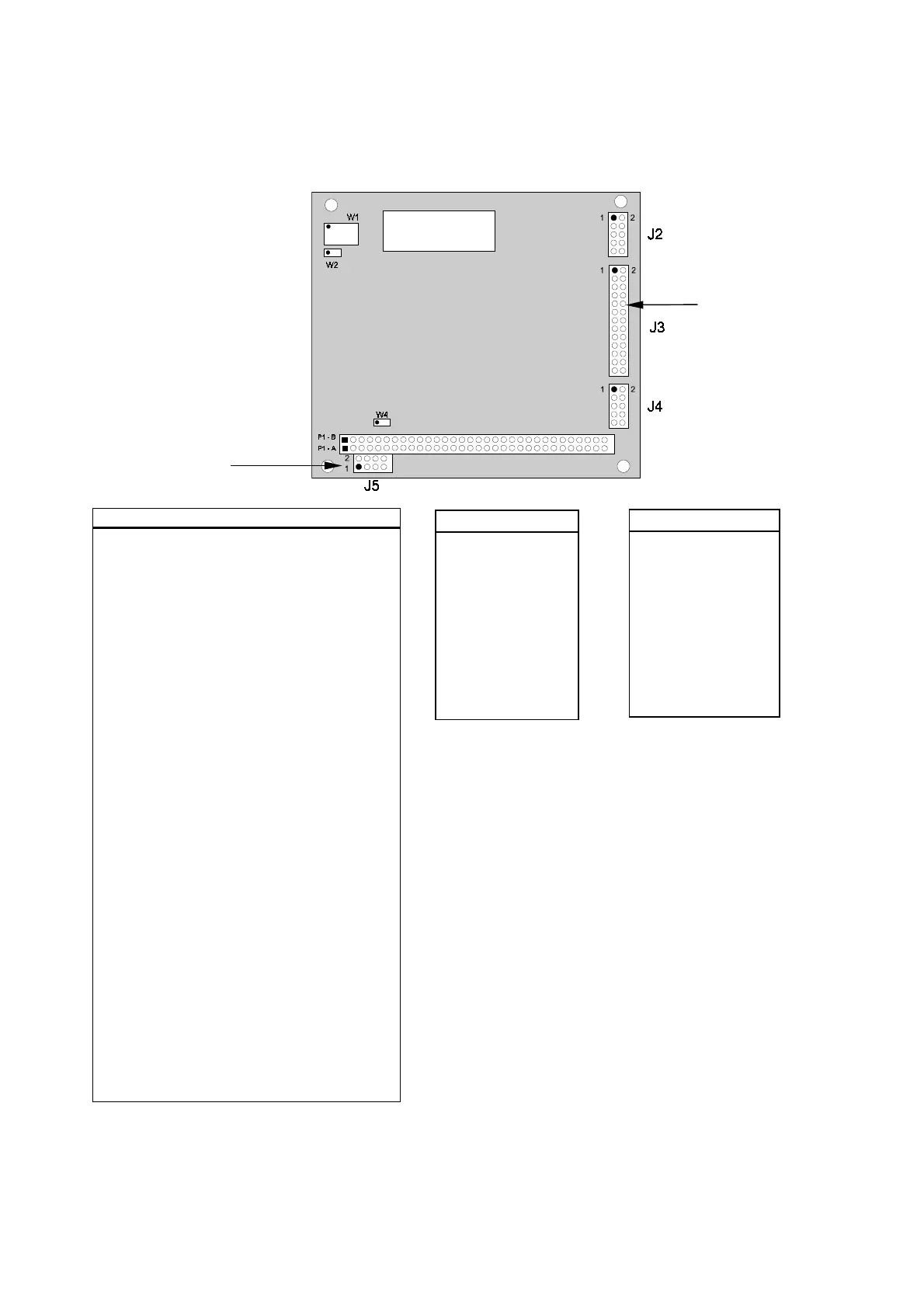
6.3 PC/104 Connector and Jumper Locations
Pin Name Pin Name
A1
-IO CHCHK
B1
GND
A2
SD7
B2
RESET
A3
SD6
B3
+5V
A4
SD5
B4
IRQ2
A5
SD4
B5
-5V
A6
SD3
B6
DRQ2
A7
SD2
B7
-12V
A8
SD1
B8
N/A
A9
SD0
B9
+12V
A10
I/O CRDY
B10
N/A
A11
AEN
B11
-SMEMW
A12
SA19
B12
-SMEMR
A13
SA18
B13
-IOW
A14
SA17
B14
-IOR
A15
SA16
B15
-DACK3
A16
SA15
B16
DRQ3
A17
SA14
B17
-DACK1
A18
SA13
B18
DRQ1
A19
SA12
B19
-REFRESH
A20
SA11
B20
CLK
A21
SA10
B21
IRQ7
A22
SA9
B22
IRQ6
A23
SA8
B23
IRQ5
A24
SA7
B24
IRQ4
A25
SA6
B25
IRQ3
A26
SA5
B26
-DACK2
A27
SA4
B27
T/C
A28
SA3
B28
BALE
A29
SA2
B29
+5V
A30
SA1
B30
OSC
A31
SA0
B31
GND
A32
GND
B32
GND
PC-104 Bus Connector
PC/104 Board
Not used in
SMT-200
Not used in
SMT-200
Byte Wide S0
Component Side
Pin Name
1
DCD
2
DSR
3
RXD
4
RTS
5
TXD
6
CTS
7
DTR
8
RI
9
GND
10
Key Pin
Serial Port
Connector (J2)
Pin Name
1
Speaker +
2
-Bat
3
Reset Switch
4
N/C
5
Kbd Data
6
Kbd Clk
7
Kbd Gnd
8
Kbd Pwr
9
+Bat
10
Power Good
Utility Connector (J4)
W1 - Byte-wide (S0) configuration
W2 - Byte-wide (S0)configuration
W4 - 12V flash programming power