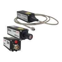
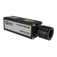
METIS M308 / M309 / M313 / M316 / M318 / M323 / H309 / H316 / H318 (12-pin)
Electrical Connection
11
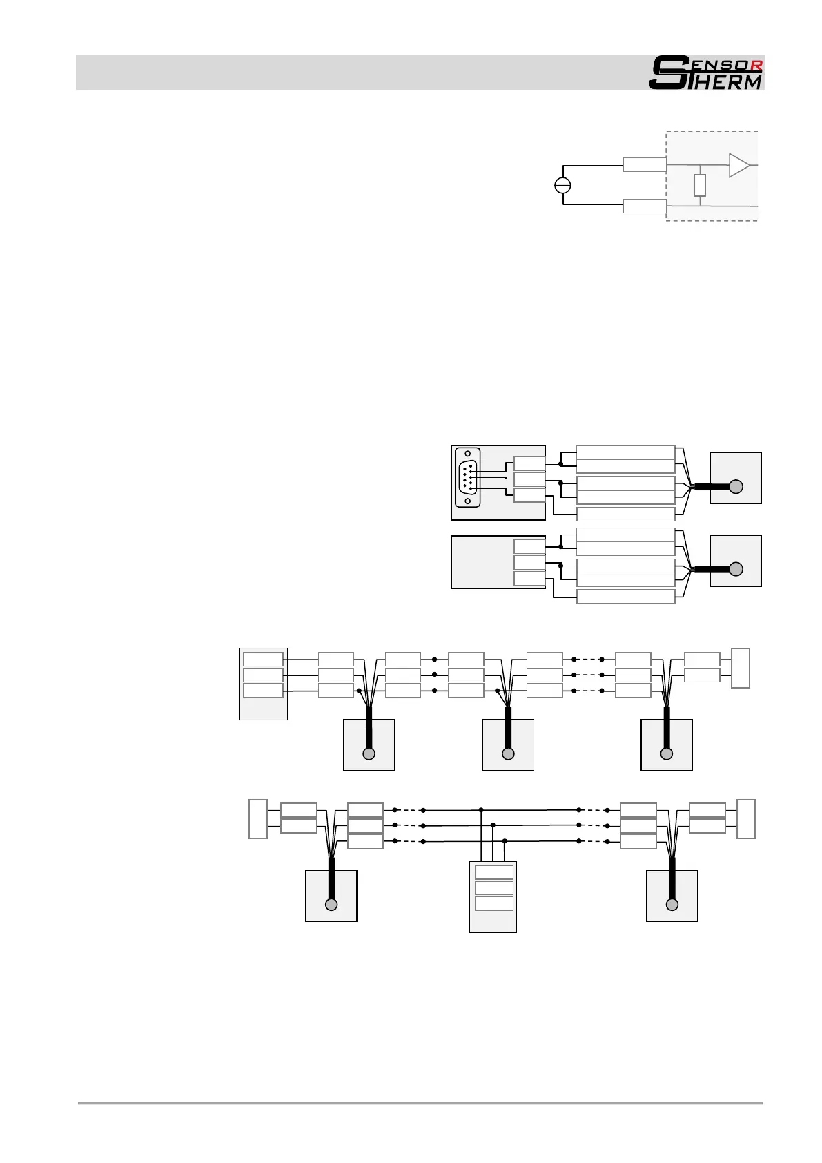
Analog input (only M3): About a 0–20 mA current source (e.g.
via a setpoint generator), some parameters can be adjusted ex-
ternally between their smallest and largest setting value (settings
via SensorTools software Configurable Inputs / Outputs
Analog input):
- Emissivity (0 mA = 0.05; 20 mA = 1.2)
- Setpoint at devices with PID controller (0 mA = zero scale
temperature, 20 mA = full scale temperature)
- Measuring distance at M3 devices with motorized focus (0 mA = shortest distance, 20 mA = wid-
est distance)
4.1.5 Serial Interface RS232 / RS485 (M3: switchable RS232 / RS485; H3: only RS485)
The serial interface is used for digital communication of the pyrometer with another computer, for exam-
ple a PC for data transmission to the software SensorTools.
The maximum transmission speed (in Baud) is limited by the cable length; it is halved with each dou-
bling of the transmission path.
RS232: about 7 m cable length with 19.2 kBd. Adjustable are values from 4.8 to 115.2 kBd.
RS485: about 2 km with 19.2 kBd. Adjustable are values between 4.8 and 921.6 kBd.
Connecting one pyrometer via
RS232 or RS485:
In a short RS232 or RS485 connection to the mas-
ter (computer receiving the data), the pyrometer is
connected directly as a point-to-point connection
with the master.
It is advantageous to connect all interface cables
in order to avoid reflections.
Connecting several pyrometers via RS485:
For a reflection-free operation with longer cables,
pay attention to the correct cable termination. Termination at the physical bus is on front and rear.
Master at the
beginning:
Master in the
middle:
When operating multiple devices (up to 32 are possible), each device needs to assign its own address
(directly on the device or via software SensorTools), under which it can be addressed later. For this
purpose, initially, each device must be connected individually and provided with an address (00-97). Af-
ter that, all devices can be connected.
If specific parameters for all devices should be changed simultaneously, the global address 98 is used
(there is no response from the device). If the address of a device is unknown, you have the opportunity
to address each device independently of the set address with the global address 99 (connect only one
device).
Terminating
resistor 120 Ω
Terminating
resistor 120 Ω
in the master
or manually
Terminating
resistor 120 Ω
Terminating
resistor 120 Ω
Setpoint input
via external
0...20 mA
 Loading...