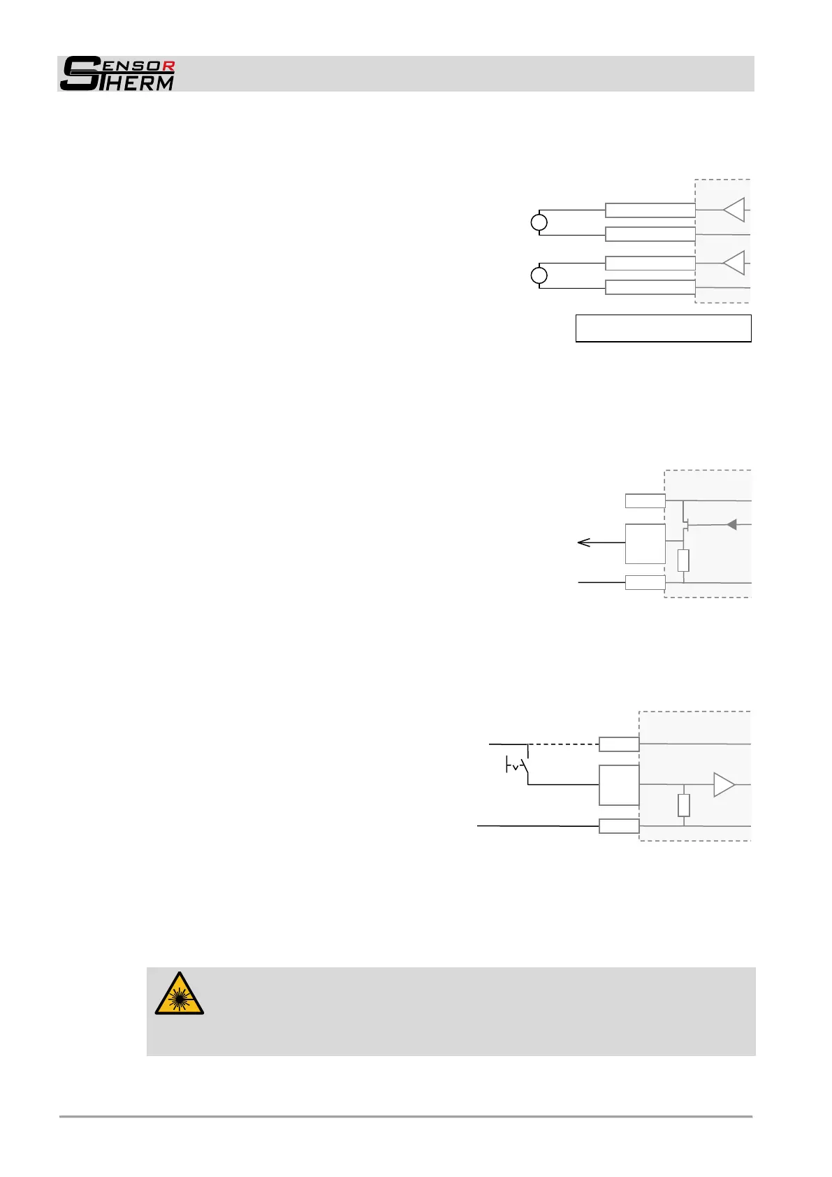
METIS M308 / M309 / M313 / M316 / M318 / M323 / H309 / H316 / H318 (12-pin)
Electrical Connection
10
+I
OUT1
-I
OUT1
+I
OUT2
-I
OUT2
Note: The outputs are galvanically
isolated from the supply voltage.
4.1.3 Analog Output 1 and 2
The analog outputs are adjustable (e.g. for a temperature display device):
0–20 mA or 4–20 mA
Analog output 1 always provides the measured temperature
(always the temperature displayed on the device display or the
software control window in SensorTools, see also 7.2.2 Con-
trol window).
(Note: With older firmware versions, the same settings are
possible as at analog output 2. A firmware update to the latest
version eliminates this possibility and prevents, that the output
of analog output 1 is accidentally different to the displayed
temperature signal. Firmware update see section 8).
Analog output 2 can be assigned to provide different signals:
- Measured temperature (always the temperature selected and displayed on the device display and
the software control window; also see 7.2 and 7.2.2 in SensorTools).
- Device temperature
- Manipulated variable of the controller output (when equipped with PID controller).
4.1.4 Configurable Inputs / Outputs
3 ports are each available as:
Digital output: output of a switching signal (invertible, see under
7.2.3 Various settings Logic NO / NC) at:
- Limit switch when a certain temperature threshold is exceed-
ed or falling below
- Material detection (only M3): turns on when exceeding the
beginning of temperature range
- Device ready to operate (device ready and error-free after self-test)
- Exceeding the maximum allowed internal device temperature
- Controller activity (only when equipped with PID controller)
Digital input: A voltage pulse of 24 V (exception: continuous voltage at "Activate controller"), pulse
length adjustable via software (minimum 3 ms,
factory settings 100 ms) under 7.2.3 Configu-
rable Inputs / Outputs debounce time ena-
bles:
- Clear of maximum value storage (see 6.3.2)
- Start controller (when equipped with PID con-
troller, see 7.2.4).
- Activate controller: The control process is ac-
tivated as long as voltage at the terminal is pre-
sent.
- Load pyrometer configuration (devices with PID controller also control parameters) (see under
7.2.3 Configurable Inputs / Outputs “parameter selector” or 7.2.5 Setups).
- Switch on / off laser targeting light (when equipped with laser targeting light)
(the targeting light will automatically switched off after 3 minutes if it is not switched off manually.
Adjustable via software under 7.2.3 Device Settings Laser targeting light settings).
CAUTION, Laser Radiation, Laser Class 2:
Never look into the direct or reflected laser beam.
Do not point the laser to anyone.
If laser radiation hits the eye, the eyes must be intentionally closed and the head
immediately moved out of the beam.
 Loading...