METIS M308 / M309 / M313 / M316 / M318 / M323 / H309 / H316 / H318 (12-pin)
Configuring the Pyrometer
23
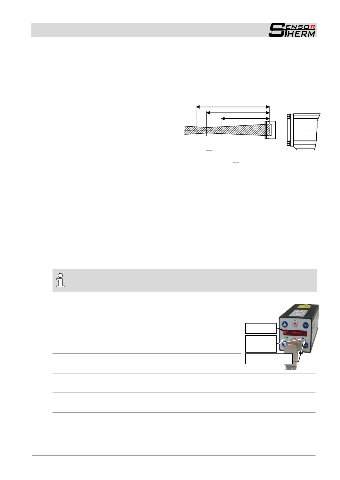
5.6.7 Calculation of the Spot Size Diameter outside the Focused Distance
The spot size diameter determines the area on the measurement object from which 90% of the temper-
ature radiation is detected by the pyrometer; therefore the spot size tables specify spot sizes for differ-
ent measuring distances (or focused distances).
For calculating intermediate values in front of and behind the focused measuring distance, the following
formula can be used or the spot size calculator integrated in SensorTools (see 7.4):
a Focused distance
M Spot size diameter in the focused measuring
distance
a
1
Measuring distance longer than focused
measuring distance
M
1
Resulting spot size on measuring distance a
1
a
2
Measuring distance shorter than focused
measuring distance
M
2
Resulting spot size on measuring distance a
2
D Aperture (specifies the spot size directly on
the optics’ lens, it differs depending on the
optics pull-out. The largest value applies at a fully extended optics, the lowest value is with inserted
lens)
6 Configuring the Pyrometer
The pyrometer is configured and adjusted to the measuring task via the adjustment buttons on the back
of the device. When connected to a PC, all settings also can be made using the supplied SensorTools
software (see 7, SensorTools software) and, in addition, settings for the configurable inputs / outputs
can be made; this is not possible with the device keys.
Further it is possible to communicate via interface commands directly to the pyrometer (see 11, Inter-
face commands). The commands can be used for writing an own control or can be entered via a termi-
nal software.
INFO to baud rate: The factory setting of the baud rate is set to 115 kBd to ensure also at
longer interface cables a working data transfer. For data transmissions with the highest speed,
baud rate and buffer mode must be adjusted (see 7.2.3.4)
6.1 Displays on the Device
Display in measuring mode
T: 0850.6°C Current measuring temperature (example)
T: – – – – Measuring temp. below beginning of temperature range
T: OVER Measuring temperature above end of temperature range
– – – – – – – – – – Device display set to „suppressed“ (see 7.2.3)
Display in adjustment mode (PAR key)
MESSPARA.> Depending on the selected parameter, see 6.3
Display of the measuring distance „a“ (devices with motoized focus optics: Press the arrow keys)
a: 1500mm Current measuring distance or focus distance (example)
LEDs 1, 2, 3 (active digital outputs)
Green: Indicates an activated digital output (see 4.1.4 Configurable inputs / outputs)
LED 4 (operating status LED)
Orange: During initialization and self-test phase (M3 ca. 2 s; H3 during the initialization and
thermostatic phase for ≤ 3 min.)
Green: The unit is ready for operation.
Red: in case of a device error.
 Loading...