METIS M308 / M309 / M313 / M316 / M318 / M323 / H309 / H316 / H318 (12-pin)
SensorTools Software
31
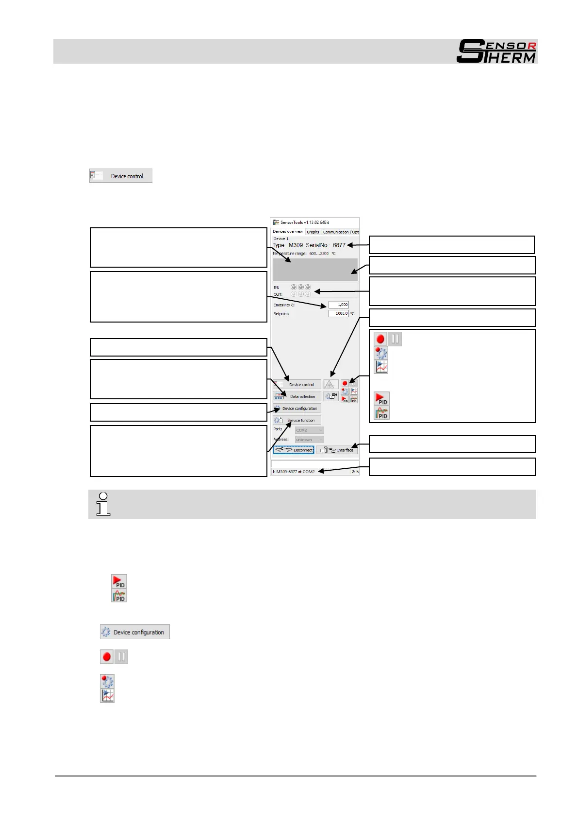
An identified pyrometer directly shows temperature information (numerically in this device overview win-
dow as well as in the control window, and graphically in the graph-tab).
Additionally the internal device temperature (DT) can be read-out.
This device overview window provides a measured value indication with basic measurement parameter
settings.
A separate control window (see 7.2 and 7.2.2) additionally provides all available meas-
urement-relevant functions and settings).
It is useful when switching to a different tab (e.g., in the graph representation).
INFO for settings on the device: a pyrometer connected to the software has blocked push
buttons. "KEY LOCK" appears when pressing a key.
Input boxes:
The emissivity must be taken into account during the measurement and adapted at the pyrometer
for the respective measuring material in order to obtain correct measured values (also see 6.3.1).
The setpoint for devices with PID controllers, see 7.2.4)
- Via the PID start button the control process can be started directly.
- The control parameters can be defined in the controller window (see 7.2.4).
Device settings are made here:
Via the device configuration basic device settings are made (see 7.2.3).
The recording function is used, as also in the graph window, to record the transferred meas-
ured value data for subsequent analysis to the hard disk (also see under 7.2.1 Information field).
opens the Data recording settings (under chapter 7.2.1)
The playback button opens the SensorTools viewer (see 7.3) to display the last measured and,
if necessary, the control values since the device was connected.
Separate control window (see 7.2.2)
Serial interface settings (see 7.2.3.3)
record measured value data
Data recording settings
Data Playback
Only devices with PID controller:
Start PID controller
Control parameters (see 7.2.4)
Device settings (see 7.2.3)
Data collection: Transfer the measured
value data from the pyrometer to the
PC (see 7.2.3.4).
Back up, print or restore device param-
eters or create service files for remote
diagnostics in case of problems (see
7.2.3.2).
Device and port information
LED symbol for status of the digital
inputs / outputs (see 7.2.3.1)
internal device temperature
Input boxes
emissivity (see 6.3.3) and
setpoint for devices with PID controller
(see 7.2.4).
Measured temperature
(“Under” at temperatures below begin-
ning of the temperature range)
 Loading...