R301 RF POWER SUPPLY OPERATOR’S MANUAL
Display
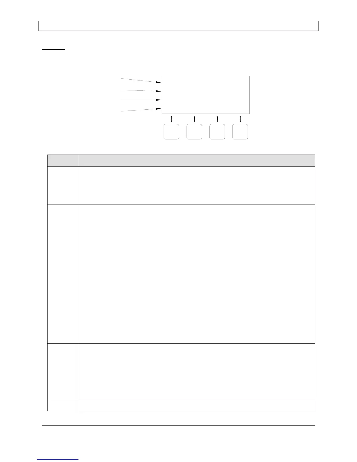
The front panel display shows the operational status of the R301 RF Power Supply and
provides legends for the keypad.
Line Description
1 Power Display Line
Displays power setpoint and reflected power when the RF Output is disabled.
Displays forward power (or load power) and reflected power when the RF output
is enabled
2 Status Display Line
Displays the current control source, power control mode, exciter mode and
operational alarms. Operational alarms are flashed on the extreme right side of
the line (see the problem solving section for alarm details).
[CONTOL SOURCE] [POWER CONTROL MODE] [EXCITER MODE] [ALARM]
Control Source:
Panel = Front Panel Control
Analog = Analog Interface
Serial = Serial Interface
Power Control Mode:
PWR = Forward Power Leveling (internal power sensor)
PLS = Pulsing Enabled (internal power sensor)
VLT = Voltage Control (external feedback)
Exciter Mode:
MST = Master (internal frequency source)
EXT = External (external frequency source)
3 User Configurable Display Line
In RUN mode:
Displays DC Voltage Probe or RF Voltage Probe output
(User enabled or disabled)
In PROGRAM mode:
Displays a programmable parameter and its current setting.
4 Keypad Menu – button legends change depending on mode
LINE 1
LINE 2
LINE 3
LINE 4
SET: 0W REF:
PWR
DOWN
PANEL CONTROL
PGM
PANEL
UP
MST
0W
ENT
Page 11
Seren IPS Inc.
6100130000 Rev. 0.05
 Loading...