R301 RF POWER SUPPLY OPERATOR’S MANUAL
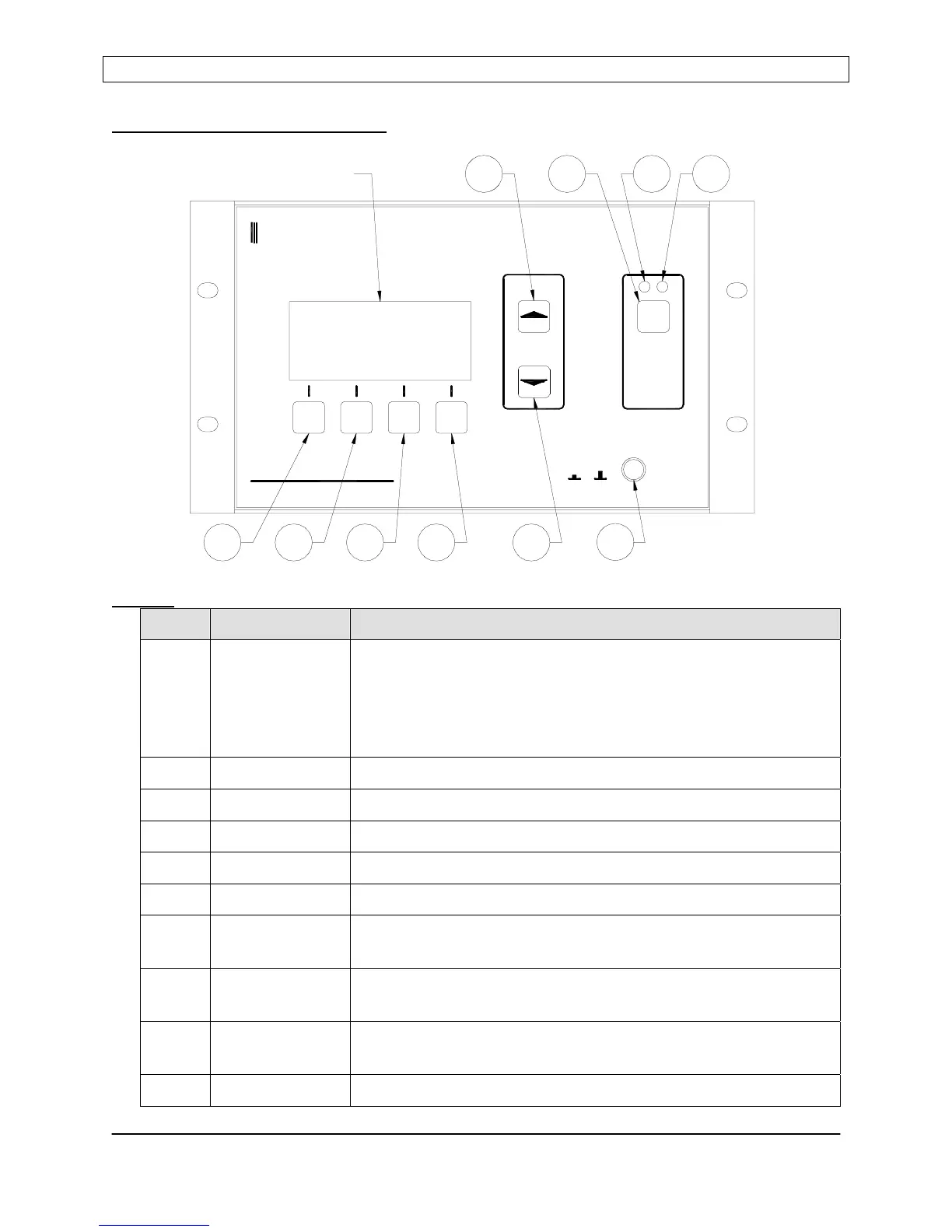
Front Panel Controls and Display:
Buttons
Item Name Description
1 Program/Run Toggles the R301 RF Power Supply between the RUN mode
and PROGRAM mode. In Program mode, display line 3
changes to show Programmable Menu Entry Options. The
button legend changes from “PGM” to “RUN” when in the
Program mode.
2 Down Moves down the programming menu
3 Up Moves up the programming menu
4 Enter Programs (saves) changes made to a parameter
5 Value Up Changes Parameter Value - Increment
6 Value Down Changes Parameter Value - Decrement
7 RF ON/OFF Enables/Disables the RF output in “local” mode, disables the
RF output in any operational mode.
8 RF ON
Indicator Lamp
Glows RED when the RF Output is enabled (on).
9 RF OFF
Indicator Lamp
Glows BLUE when the RF output is disabled (off)
10 Power AC Mains power enable/disable
RADIO FREQUENCY POWER SUPPLY
R301
POWER
I O
SEREN
Industrial Power Systems
ON / OFF
RF
0W0W REF:SET:
ENT
PWR
DOWNPGM
PANEL
UP
MST
DISPLAY
5
897
10
6
4
3
21
Page 10
Seren IPS Inc.
6100130000 Rev. 0.05

 Loading...