R301 RF POWER SUPPLY OPERATOR’S MANUAL
TYPICAL INTERFACE CONNECTIONS
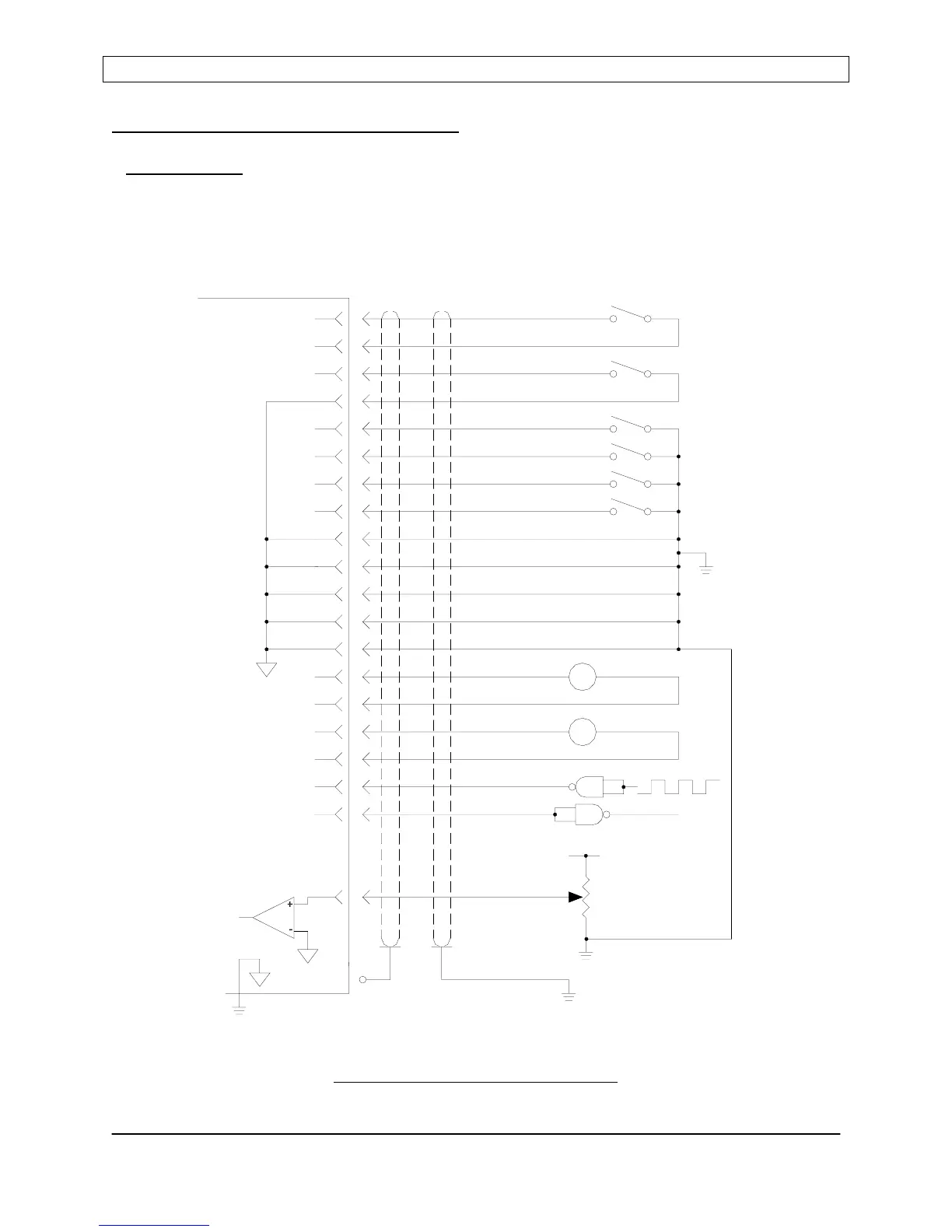
Analog Control
There are many possible analog interface wiring schemes. Basic analog interface connections
are diagrammed below. Refer to the Analog Interface Connector pin list in the Rear Panel
Controls and Connections section for signal details. Use shielded cable for all
interconnections.
Typical Analog Interface Connections
Page 45
Seren IPS Inc.
6100130000 Rev. 0.05
13
CHASSIS
SHELL
8
7
SETPOINT
SHIELD
RFENABLED*
GATE
+10VDC
+5VDC OR
9
11
23
22
10
21
18
17
16
POWER SUPPLY
R301 RF
5
6
4
3
15
14
2
1
GND
REF MON
REF RET
FWDRET
FWD MON
V
+
V
+
GND
GND
GND
GND
-
-
GATEN*
SLAVE*
PWR/VLT*
RFON*
INTERLOCK
INTERLOCK-RTN
MAINS INTLK2
MAINS INTLK1