R301 RF POWER SUPPLY OPERATOR’S MANUAL
External Feedback with Probe Inverter Option
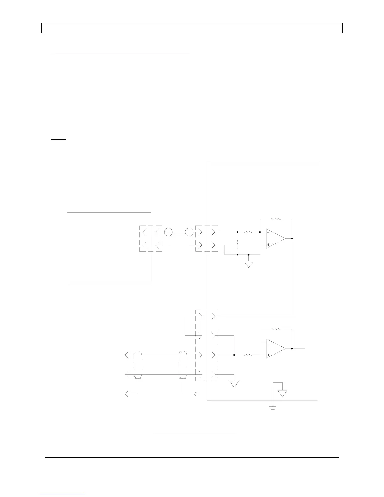
The R301 RF power supply’s external feedback input (FEEDBACK, analog interface
connector pins 12 and 24) only accepts a positive (+) polarity signal. The Probe Inverter
feature allows the R301 RF Power Supply to utilize a negative polarity feedback signal.
Connect the negative polarity external feedback signal to the rear panel “DCP” BNC connector
and connect Analog Interface connector pin 24 to pin 25.
If desired, the inverted probe signal may also be routed to the user’s system for monitoring
purposes. Use analog interface connector pins 12 (FEEDBACK) and 18 (GND). Connections
must
be made with shielded cable to prevent interference to the feedback signal.
Probe Inverter Connections
Page 46
Seren IPS Inc.
6100130000 Rev. 0.05
(IF DESIRED)
SHIELD
SHELL
CHASSIS
INTERFACE
ANALOG
DCP
WITH PROBE INVERTER
R301 RF POWER SUPPLY
TO SYSTEM
PROBE SIGNAL
(MATCHING NETWORK)
PROBE SOURCE
25
12
24
1X
100K