R301 RF POWER SUPPLY OPERATOR’S MANUAL
External Feedback with Seren IPS AT-Series Matching Networks
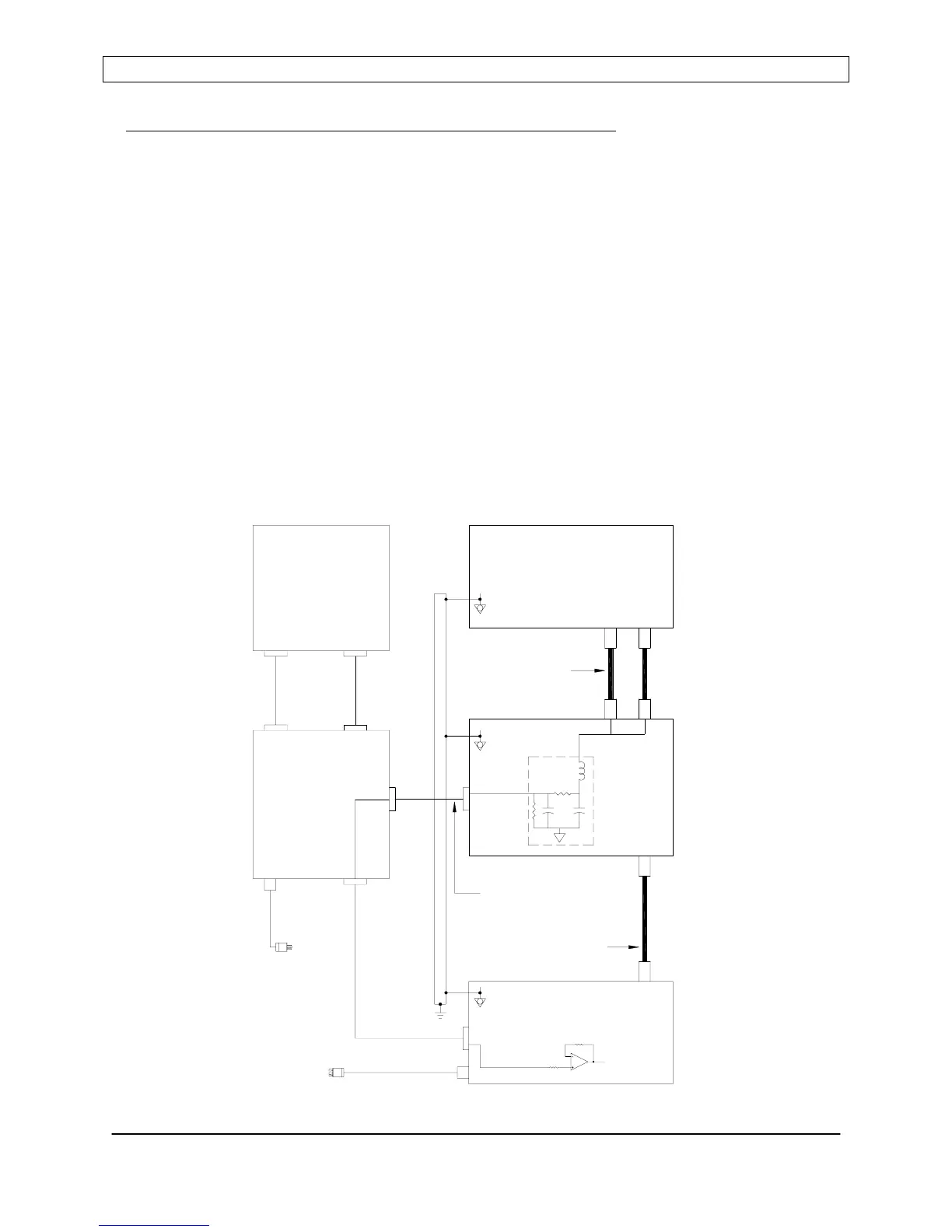
External feedback is also available when using a Seren IPS Inc. AT-Series automatic
impedance matching network (purchased separately). In this application, there is no
connection between the R301’s Analog Interface connector pins 24 and 25, and there is no
connection to the R301’s rear panel PROBE connector.
The external feedback signal is derived in the AT-series matching network, via a DC Probe
circuit. The DC Probe’s output is passed through the AT-Series control cable to the MC2
Matching Network Controller. The external feedback signal (DC Probe) may be displayed on
the MC2 Controller’s front panel. When used with an optional interconnect cable, connecting
the MC2 Controller’s “TO GENERATOR” connector the R301’s Analog Interface connector,
the external feedback signal (DC Probe) is routed to the R301’s External Feedback input.
Refer to the diagram below.
In addition, the MC2 controller can display Forward and Reflected power and can act as an
interconnection hub for the user’s system. For full details, refer to the MC2 Matching Network
Controller Operator’s Manual or contact a Seren IPS Inc. customer support technician.
External Feedback with AT-Series Matching Network
GENERATOR
CONTROLLER
MAINS
POWER
CONTROLLER
MAINS
POWER
MC2
ANALOG
CONTROL
TO MATCH
CONTROL
FEEDBACK
EQUIPOTENTIAL
ANALOG
INTERFACE
12
TERMINAL
BONDING
R301 RF POWER SUPPLY
AT-SERIES
COAXIAL CABLE
CONTROL
CABLE
RF
OUTPUT
RF OUTPUT
PLASMA CHAMBER
OR OTHER LOAD
OR DIRECT INTERNAL
MATCHING
NETWORK
TO
SYSTEM
FROM
PROBE
CONTROL
CONNECTION
EQUIPOTENTIAL
TERMINAL
BONDING
DC
GENERATOR
TO
SYSTEM
EQUIPOTENTIAL
COAXIAL CABLE(S)
BONDING
TERMINAL
AT-SERIES
RF
INPUT
NETWORK
MATCHING
Page 47
Seren IPS Inc.
6100130000 Rev. 0.05