R301 RF POWER SUPPLY OPERATOR’S MANUAL
9. Serial Interface Connector
The serial interface provides remote control and monitoring of the R301 RF Power
Supply via a computer. Serial interface protocol is RS-232. Baud rates are selected via
the front panel.
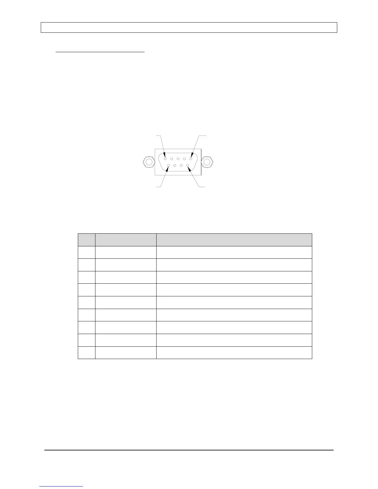
Connector Type: 9 pin “D” female
For serial operation details, see the Serial Commands section of this manual.
SERIAL CONNECTOR
PIN 9
PIN 5
PIN 6
PIN1
Pin Signal Description
1 No Connection No Connection
2 TXB Transmit Data
3 RXB Receive Data
4 No Connection No Connection
5 COMMON Common Return (GND)
6 No Connection No Connection
7 CTS Clear To Send
8 RTS Request To Send
9 COMMON Common Return (GND)
Page 44
Seren IPS Inc.
6100130000 Rev. 0.05