R301 RF POWER SUPPLY OPERATOR’S MANUAL
MONITOR Output Circuit
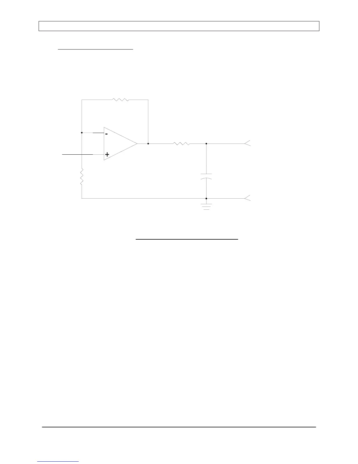
Analog output, selectable 0 to +5VDC or 0 to +10VDC range via front panel controls.
Normal function is forward or reflected power monitoring, but can be configured to pre-
position Seren IPS Inc. AT-Series Matching Networks. See the Programming Menu
reference for additional details.
Figure 5: MONITOR Output Circuit
Page 43
Seren IPS Inc.
6100130000 Rev. 0.05
TLO74
MONITOR10
0.1uF
RETURN
MONITOR
OUTPUT
(GND)