R301 RF POWER SUPPLY OPERATOR’S MANUAL
Figure 2: TTL-Compatible Input Circuits
SETPOINT Input Circuit
High-impedance, high Common-Mode Rejection Ratio, differential analog input. Input
voltage range is software selectable 0 to +5.0VDC or 0 to +10.0VDC via the front panel
controls. NOTE: The setpoint return signal (GNDI, pin 16, 17, 18, or 21) MUST
be
referenced to common or ground at the setpoint voltage source (system controller) or the
RF output power will behave erratically.
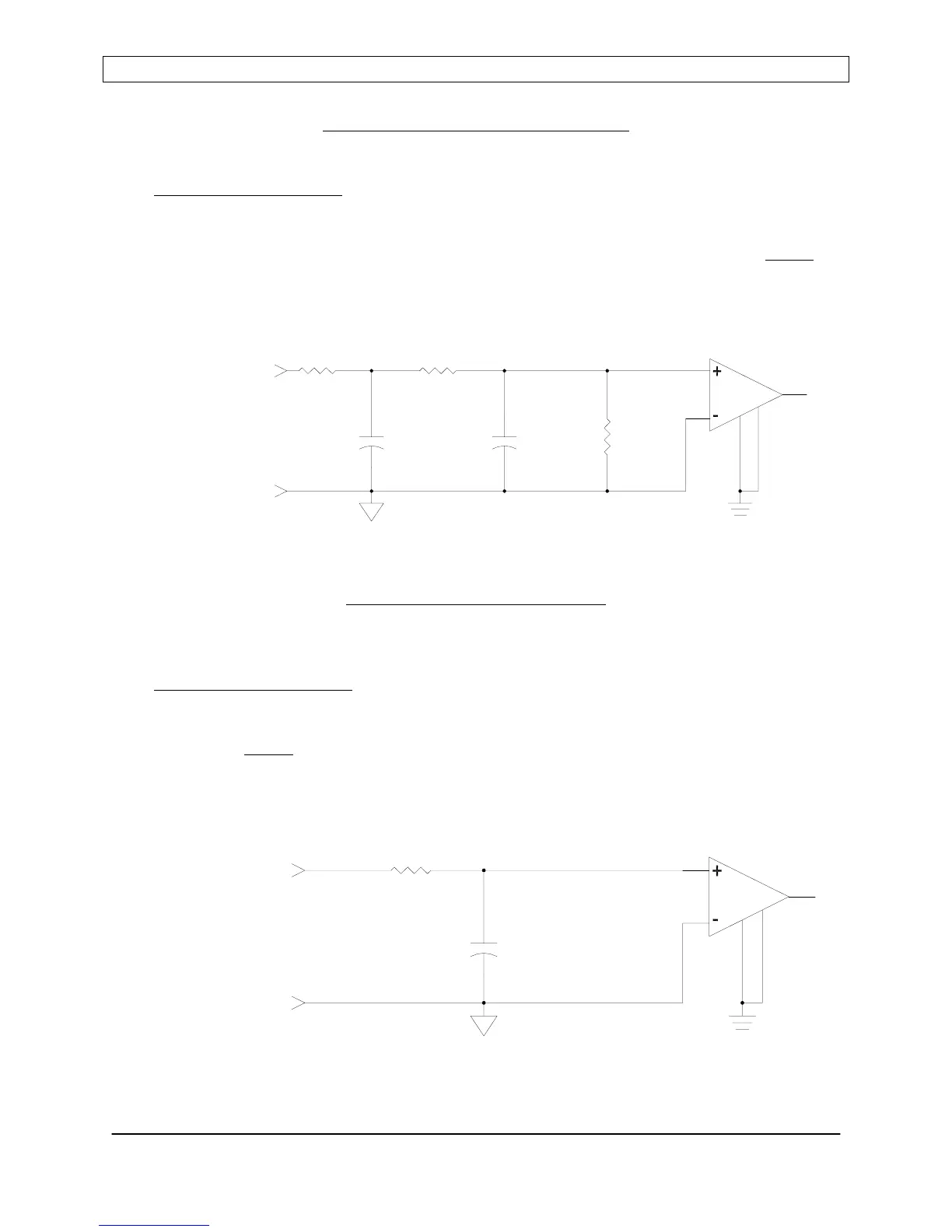
Figure 3: SETPOINT Input Circuit
FEEDBACK Input Circuit
High-impedance, high Common-Mode Rejection Ratio, differential analog input. Input
voltage range is 0 to +10.0VDC. NOTE: The feedback return signal (GNDI, pin 16, 17,
18, or 21) MUST
be referenced to common or ground at the feedback voltage source
(Voltage Probe) or the RF output power will behave erratically.
Figure 4: FEEDBACK Input Circuit
Page 42
Seren IPS Inc.
6100130000 Rev. 0.05
INPUT
SETPOINT
0.1uF
100
0.1uF
10K
INA117
SETPOINT
RETURN
(GNDI)
100K
0.1uF
INPUT
FEEDBACK
RETURN
(GNDI)
FEEDBACK
100
INA117