R301 RF POWER SUPPLY OPERATOR’S MANUAL
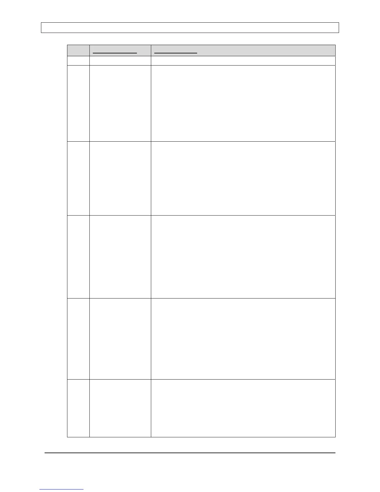
PIN
SIGNAL NAME DESCRIPTION
This signal is active in Panel, Analog, or Serial control modes
2 INTERLOCK External Interlock. TTL – compatible input, active low, with an
internal pull-up resistor.
A contact closure between pin 2 and pin 15 or a TTL “low” signal
applied to pin 2 is required before RF output can be enabled.
An open circuit or a TTL “high” signal applied to pin 2 while the
RF output is enabled, will cause the RF output to turn off.
An open circuit or a TTL “high” signal applied to pin 2 while the
RF output is off, will prevent the RF output from being enabled.
This signal is active in Panel, Analog, or Serial control modes
3 RFON* RF Output Enable/Disable. TTL – compatible input, active low,
edge triggered, with an internal pull-up resistor.
A contact closure between pin 3 and pin 16 or a TTL signal
transition from “high” to “low” applied to pin 3 enables the RF
output, provided Pin 2 is at TTL “low” state.
An open circuit between pin 3 and pin 16 or a TTL signal
transition from “low” to “high” applied to pin 3 disables the RF
output.
This signal is active only in “Analog” control mode.
4 PWR/VLT* Power or Voltage leveling mode select. TTL – compatible input
with internal pull-up resistor.
An open circuit or TTL “high” signal applied to pin 4 selects the
power supply’s internal power sensor for power regulation.
A contact closure between pin 4 and pin 16 or a TTL “low” signal
applied to pin 4 selects forward power regulation based on an
external feedback signal (FEEDBACK signal - Pins 12 and 24).
Refer to the controls section of the operator’s manual for
detailed instructions on how to configure and use this mode.
This signal is active only in “Analog” control mode.
5 SLAVE* Selects internal oscillator/exciter or external oscillator/exciter
(Slave Mode) as frequency source operation. TTL – compatible
input with an internal pull-up resistor.
A contact closure between pin 5 and pin 17 or applying a TTL
“low” signal to pin 5 selects external frequency source (Slave
Mode) operation. The external frequency source is connected
to the “CEX IN” connector on the rear panel.
An open circuit or TTL “high” applied to pin 5 selects the power
supply’s internal oscillator/exciter as the frequency source.
This signal is active only in “Analog” control mode.
6 GATEN* Selects Continuous Wave (CW) or Pulse Operation. TTL –
compatible input with an internal pull-up resistor.
A contact closure between pin 6 and pin 18 or applying a TTL
“low” signal to pin 6 selects pulse operation. Apply the external
pulse train to Pin 7.
Applying a logic level high to this pin or allowing this pin to float
selects continuous wave (CW) operation.
Page 37
Seren IPS Inc.
6100130000 Rev. 0.05
 Loading...