User Manual SERVOPRO PLASMA Trace N
2
Analyzer
APPENDIX 2
65
ALARM OUTPUT OPTION
With this option, two digital dry contact outputs are available for process alarms. These contacts
are always closed for fail safe purposes. They are connected to a terminal strip labeled "AL1" for
alarm #1 and "AL2" for alarm #2. One side of each relay the output is connected to the "C"
terminal, on the rear panel terminal strip. They share the same fuse used by other digital outputs.
The total current of all loads connected to digital output i.e. status, range in use; and alarms must
not exceed: 30 Vrms, 42.4 V peak or 60 Vdc, 1 Amp maximum. The alarms output contacts are
protected with snubber circuits mounted on the digital output board inside the analyzer.
When the ppm value of the sample gas exceeds the set point of alarm #1 or alarm #2 their
respective contact will open.
To enter the set point value for alarms you should go in the CONFIGURATION MENU, at page
2 (to access page 2, press F3 labeled NEXT on page 1).
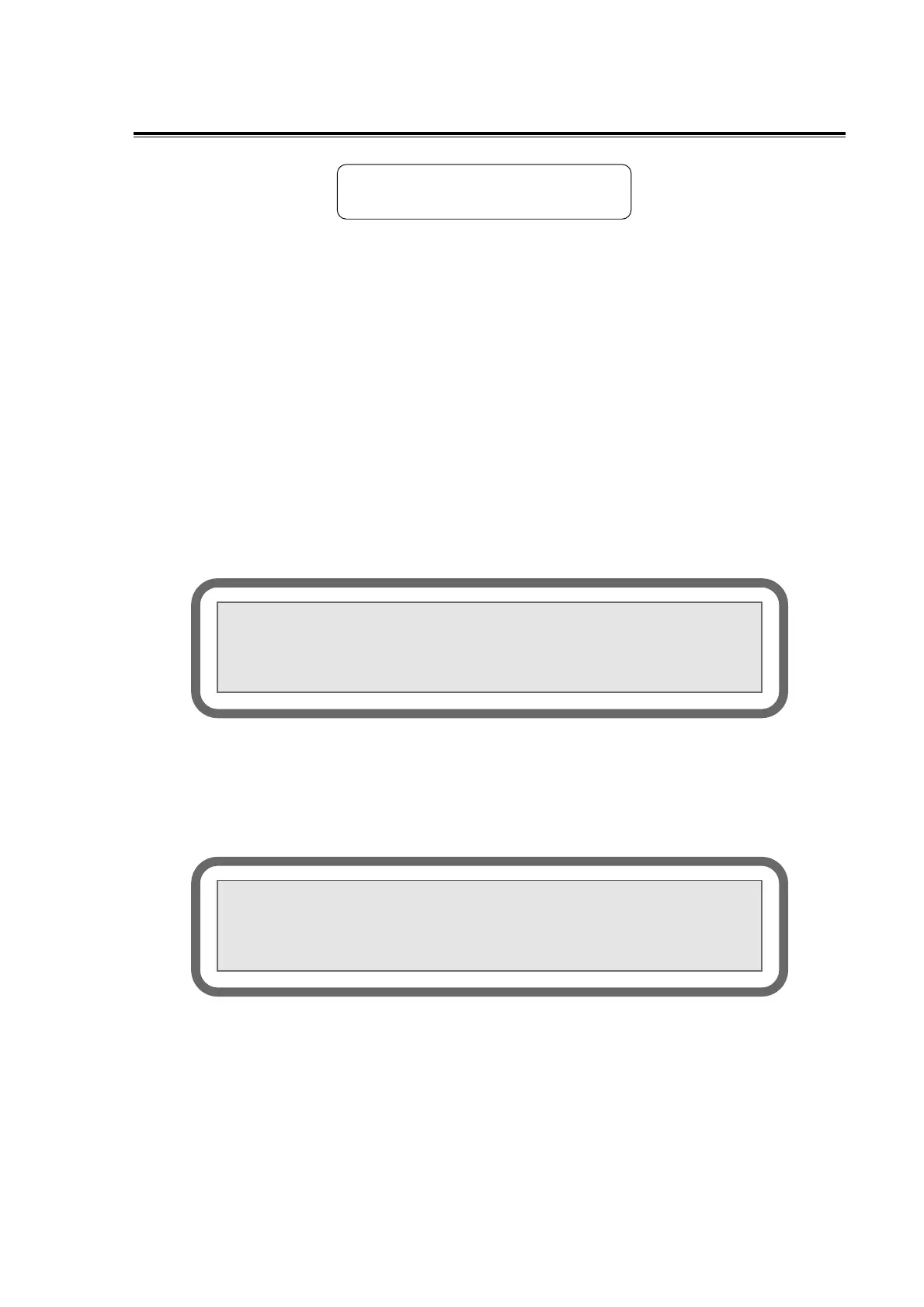
FIGURE 1 : CONFIGURATION MENU, page 2
Pressing F2 will bring up the line for entering the alarm set point for alarm #1. See figure 2
below.
FIG. 2 ENTERING ALARM #1 SET POINT
FIGURE 2: ENTERING ALARM #1 SET POINT
Enter your value in ppm with the numerical keys and confirm with the "E" key for ENTER.
Once the ENTER key is pressed, the value will be activated immediately and this value will be
displayed under ACTUAL. To exit the alarm #1 input function, press F4. This will bring up the
original page 2 of CONFIGURATION MENU (fig. 1).
<<CONFIGURATION MENU>> Page 2
F1:mA failure mode (High/Low/Off): HIGH
F2:Alarm #1 Set Point:90.0 PPM
F3:Alarm #2 Set Point:100.0 PPM
<<CONFIGURATION MENU>> Page 2
F1:mA failure mode (High/Low/Off): HIGH
Input Alarm#1:95.0 Actual:100.0
F3:Alarm #2 Set Point:100.0 PPM F4:RET