User Manual SERVOPRO PLASMA Trace N
2
Analyzer
APPENDIX 7
89
FIG 7: CALIBRATION FACTOR CALCULATION MENU
To re-span the instrument, a re-zero must have been performed before. You must then allow the span gas to flow in the analyzer.
If your analyzer has the auto-calibration option, select “SPAN” as the gas source from the CALIBRATION MODE SELECTION
MENU (FIG 2) by using the F1 key.
When this is done, let the gas stabilize, go back to the CALIBRATION FACTOR CALCULATION MENU and press F2 to re-
span the instrument. Selecting F2 will confirm the re-span of the instrument and will start the factor calculation with the gas
currently flowing. “CALIBRATION DONE” must be displayed next to “CALIBRATION STATUS”. From that point, you may
press F4 several times to exit the calibration menus.
NOTE: “WARNING: actual selected gas is” followed by the gas currently selected is displayed if this gas is not the zero gas
(SOV2 energized) when a re-zero is about to be performed or if it is not the span gas (SOV3 energized) when a re-span is about
to be performed.
The previous procedure was intended for a manual calibration in which the user controls the various steps of calibration. To
enable the analyzer to recalibrate by itself, read the following section about automatic calibration.
2.3 Automatic Calibration Mode
In this mode, the analyzer executes calibration (i.e. re-zero and re-span) at fixed intervals defined by the user. This duration is
called “TIME BETWEEN CALIBRATIONS”. When this time interval is reached, the analyzer opens the status contact and
energizes solenoid SOV2 to allow the zero gas to flow into the instrument. This gas flows during “TIME ON CAL.GAS” which
is also defined by the user. When the “TIME ON CAL. GAS” is reached, a re-zero (with the zero gas) is automatically performed.
The span gas is then selected for a “TIME ON CAL. GAS” duration after which a re-span is automatically executed (with the
span gas). Finally, the analyzer automatically re-selects the sample gas and closes back the status contact. Calibration timers are
re-settled at zero and the cycle is repeated again and again.
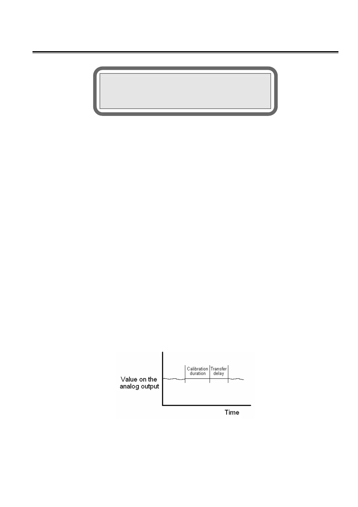
If the 4-20 mA analog output of the analyzer is set to “HOLD” mode in the CONFIGURATION MENU, the analyzer waits for
the “TRANSFER DELAY” before refreshing the 4-20 mA after the re-span has been performed. This delay gives the time to
purge the span gas out of the system and avoid undesired bumps on the 4-20mA trending. The analog output remains at the value
calculated just before the beginning of the calibration.
FIG 8: TRANSFER DELAY
<<CALIBRATION FACTOR CALCULATION>>
Measure:0.00 PPM Sample Flow:75.0 CC
RE-ZERO(F2-Yes F1-No) SPAN NOT SET
Calibration status: